TroubleshootingCLV-180
2-8
ISSUE1
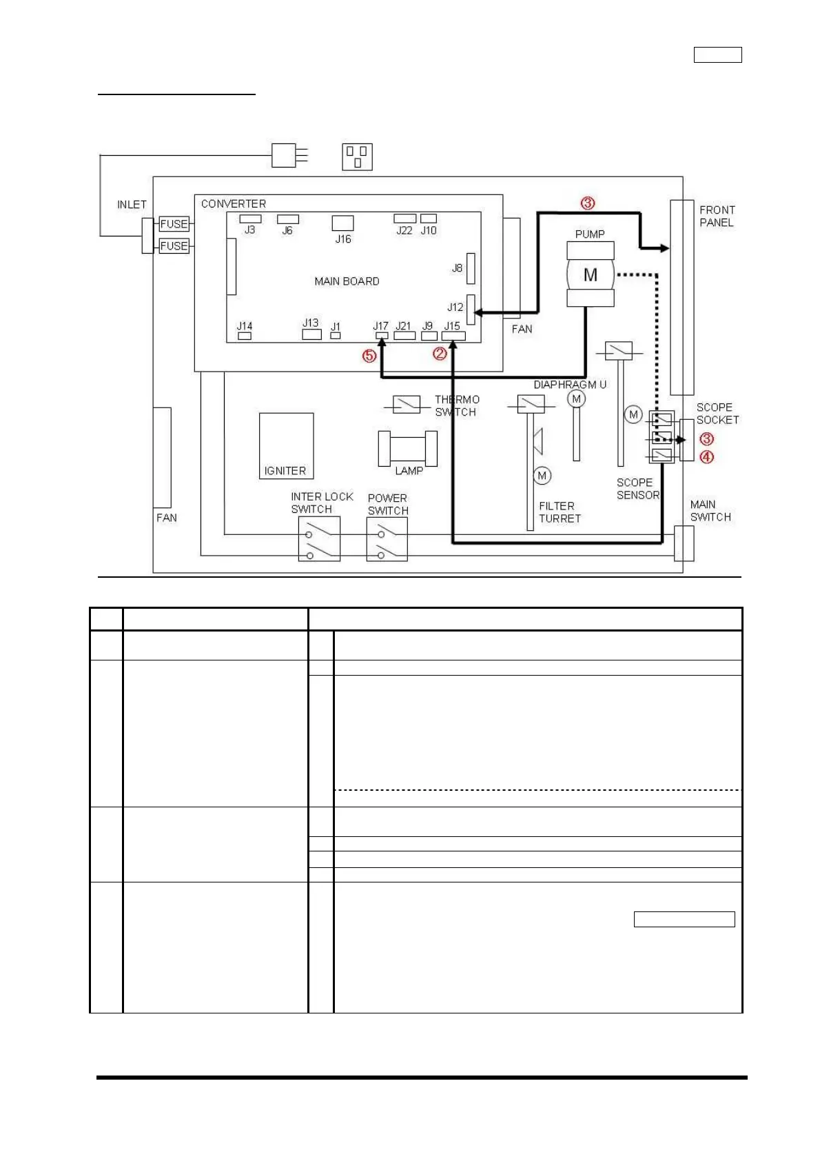
2-8 Pump malfunction
No movement of the pump, or no change in air supply volume when switching the pump ON.
2-8-1 Block diagram
2-8-2 Estimated location of failure
No
Estimated location failure Inspection Method
①
Scope 1
Confirm that scope is compatible GI scope.
*EVIS 100,130, 160, 180 Series
1
Set Pump Switch to "H".
Confirm following status of J15 on Main Board:
J15 on MAIN BOARD
When GI scope is connected
Pin 2: LOW
Pin 5: HIGH
Pin 8: LOW
Pin 9: GND
* HIGH: approx. 5 V
②
Scope Sensor
2
NO → Replace Scope Sensor
1
Verify Harness connection.
Main Board (J12) <--> Front Panel
2
Verify hose connection.
3
Check stuffing of Reverse Stop Valve
③
Harness/
Tube
4
Verify rubber of Air Supply Mouthpiece.
④
Pump 1
Confirm that air supply pressure / volume conform standards when
changing air supply setting to L, M, and H.
Air Flow Checker
Max pressure (at H)
53.9 kPa or less (air supply pressure locked)
Volume
L: 0.5 L/min or more (output pressure: set as 19.6-20.6 kPa)
M: 0.68 L/min or more (output pressure: set as 21.6-22.6 kPa)
H: 1 L/min or more (output pressure: set as 26.5-27.5 kPa)