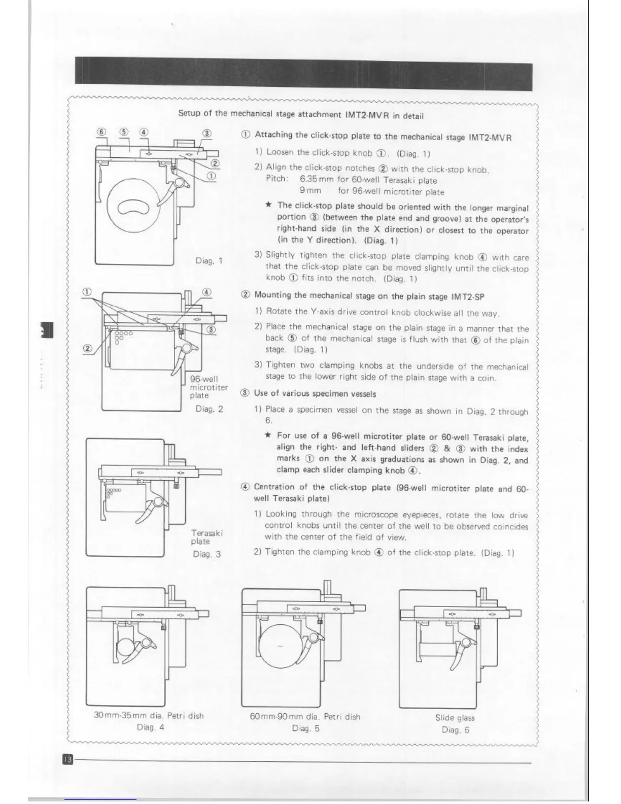
Setup of the mechanical stage attachment IMT2-MVR in detail
I-l
Diag. 1
J
30mm-35mm dia. Petri dish
Diag. 4
0 Attaching the click-stop plate to the mechanical stage IMT2-MVR
1) Loosen the click-stop knob 0. (Diag. 1)
2) Align the click-stop notches @ with the click-stop knob.
Pitch :
6.35mm for 60.well Terasaki plate
9mm
for 96-well microtiter plate
* The click-stop plate should be oriented with the longer marginal
portion @ (between the plate end and groove) at the operator’s
right-hand side (in the X direction) or closest to the operator
(in the Y direction). (Diag. 1)
3) Slightly tighten the click-stop plate clamping knob @ with care
that the click-stop plate can be moved slightly until the click-stop
knob @ fits into the notch. (Diag. 1)
@ Mounting the mechanical stage on the plain stage IMT2-SP
1) Rotate the Y-axis drive control knob clockwise all the way.
2) Place the mechanical stage on the plain stage in a manner that the
back @ of the mechanical stage is flush with that @ of the plain
stage. (Diag. 1)
3) Tighten two clamping knobs at the underside of the mechanical
stage to the lower right side of the plain stage with a coin.
0 Use of various specimen vessels
1) Place a specimen
vessel on the stage as shown in Diag. 2 through
6.
* For use of a 96-well microtiter plate or 60-well Terasaki plate,
align the right- and left-hand sliders @ & @ with the index
marks 0 on the X axis graduations as shown in Diag. 2, and
clamp each slider clamping knob 0.
@ Centration of the click-stop plate (96-well microtiter plate and 60-
well Terasaki plate)
1) Looking through the microscope eyepieces, rotate the low drive
control knobs until the center of the well to be observed coincides
with the center of the field of view.
2) Tighten the clamping knob @ of the click-stop plate. (Diag. 1)
60mm-90mm dia. Petri dish
Diag. 5
Slide glass
Diag. 6
Artisan Technology Group - Quality Instrumentation ... Guaranteed | (888) 88-SOURCE | www.artisantg.com