5
OPERATION
2-1 Control Box IX2-UCB-2
1
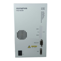
Turning Power On
(Fig. 1)
Fig. 1
Ensure that the modules to be used are connected properly. (P. 9)
1. Set the main switch @ to “ I ” (ON).
2. Ensure that the LED indicators ² corresponding to the connected mod-
ules are lit.
2
Functions of Indicator LEDs
(Fig. 1)
1. RMT: Lights only at the time of remote control.
2. ERR: Blinks in case of an error. At this time, the associated indicators
blink as described below.
3. NP to Z: Each indicator lights when the corresponding module is installed.
2-2 Hand Switch U-HSTR2
Fig. 2
1
Attaching Indication Stickers
(Fig. 2)
1. Attach each piece of the provided function indication stickers onto the
dented area @ above the button where the corresponding function is
set.
2. The indication stickers are given weak adhesive force intentionally so
that they can be removed and re-attached easily.
3. The indication stickers include two types of stickers carrying no indication
on them.
· Light shield sticker: Attach to the dented area above a button with no
function set.
· Blank sticker: Create a custom indication sticker by writing the function
name with oily ink and attach to the dented area above
the required button.
Also usable for substitution of light shield stickers when
they have run out.
Fig. 3
2
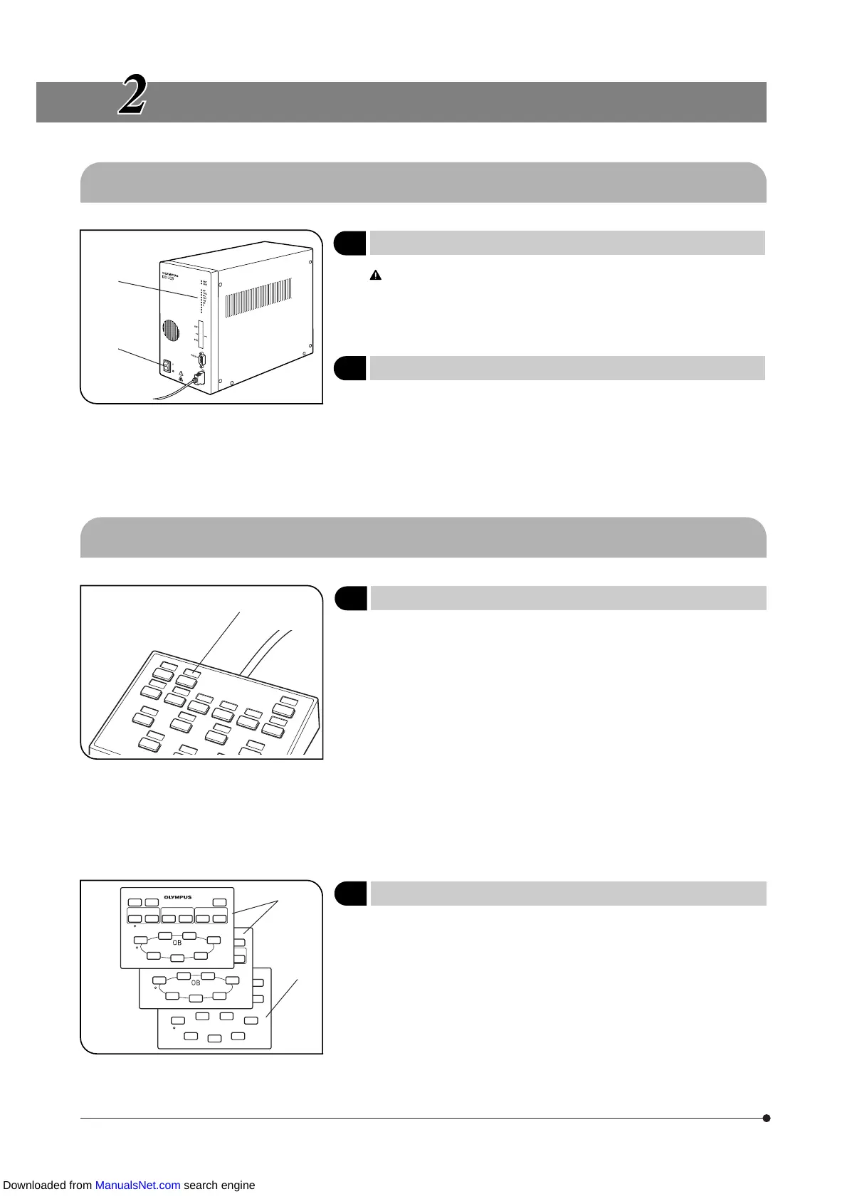
Grouping Panel Sheet
(Fig. 3)
Two sheets showing the function groups of buttons with enclosing lines
@ and a blank sheet ² are provided. Select and use the sheet that is
most convenient.
The blank sheet can be used by drawing desired grouping lines with oily
ink pen.
}Sheet 1 (the topmost sheet) has been designed for use in stand-alone
mode or when you use the buttons with their initial settings.
@
²
@
²
@
Downloaded from ManualsNet.com search engine