3
NOMENCLATURE
Make sure to connect the Olympus-specified module to each connector.
The PC in use should meet the IEC60950 requirements.
If any non-specified equipment is used, Olympus cannot guarantee any performance of the system.
Control Box IX2-UCB-2
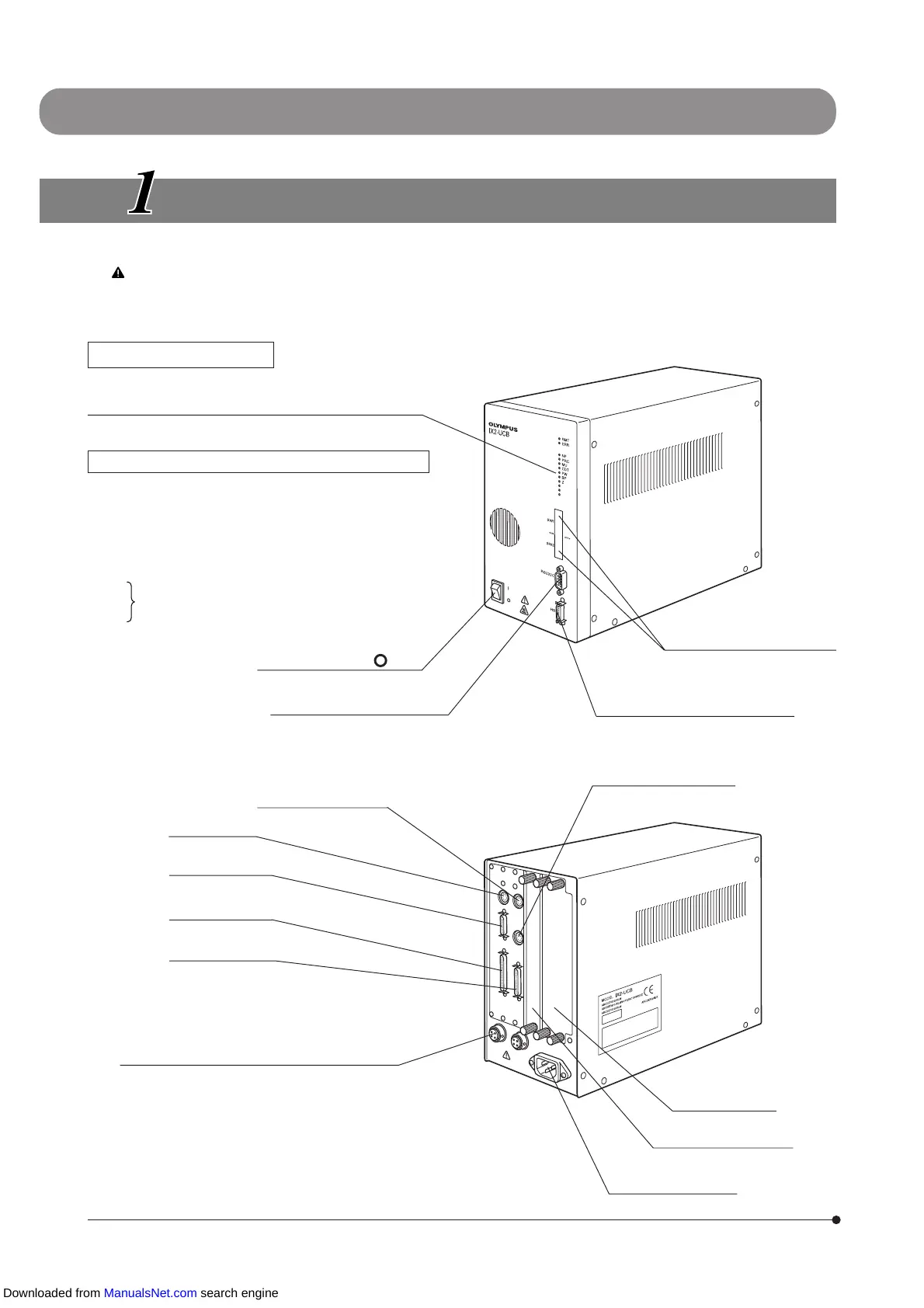
Indicator LEDs
· RMT: Lights at the time of remote control (in orange).
· ERR: Blinks in case of an error (in red).
Lights during attachment (in green)/blinks during operation.
· NP: 6-position motorized revolving nosepiece
· PRC: Motorized light path selector
· MU: Either the IX2-RFACA or U-FWR
· CDT: Either the IX2-LWUCDA or U-FWR
· FW: Either the U-FWO or U-FWR
· BP: IX2-TVRAC
· Z: U-ZPCB
·
· Spare
·
Main switch ( I : ON, : OFF)
RS232C connector (9-pin male)
PC connector
DIP switches
Used for selection of operation
settings. (p.6)
U-HSTR2 (Hand Switch) connector
RFACA/FW1 connector
MAIN 1 connector
MAIN 2 connector
MAIN 3 connector
100 W halogen lamp housing connector
(Note) The connector on the right cannot be used.
Option slot
Z board can be installed.
Option slots (2 ch)
Power cord connector
LWUCDA/FW2 connector
FW3 connector
IX2 SERIES MOTORIZED SYSTEM
Downloaded from ManualsNet.com search engine