12
IX2-UCB/U-HSTR2
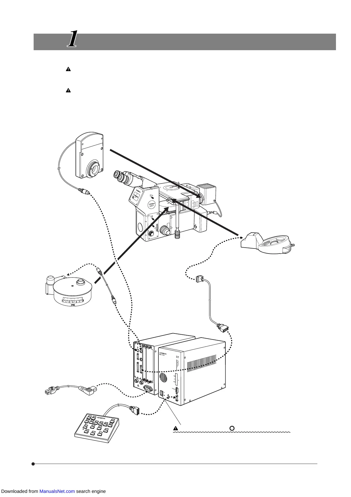
MOTORIZED SYSTEM DIAGRAM
Be sure to connect the Olympus-specified module to each
connector. If other module than specified is connected, Olympus
can no longer warrant the performance of the system.
Be sure to distribute the cables away from the lamp housing
and the surroundings (particularly, take special care to the
filter wheel). If a cable comes in contact with them, it may melt
and electric shock may result.
Motorized Revolving Nosepiece
U-D6REM
U-D5BDREM
(Note 1)
To prevent disconnection of the cables
of the motorized revolving nosepiece and
mirror unit turret, mount the provided
cable cover (for how to mount and how
to use, see next page).
Filter Wheel
U-FWR
Inverted Metallurgical
System Microscope
GX71
GX51
Motorized Mirror Unit Turret
GX-RTUA
<Mountable only on the GX71>
Connection Cable
U-REMMT
(Note 1)
Rear
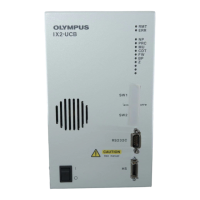
Control Box
IX2-UCB-2
Set the main switch to “ ” (OFF) before connection.
Power cord
Hand Switch
U-HSTR2
(Note 1)
Downloaded from ManualsNet.com search engine