12
2.2 Foot switch
MAJ-2301 INSTRUCTION MANUAL
Ch.2
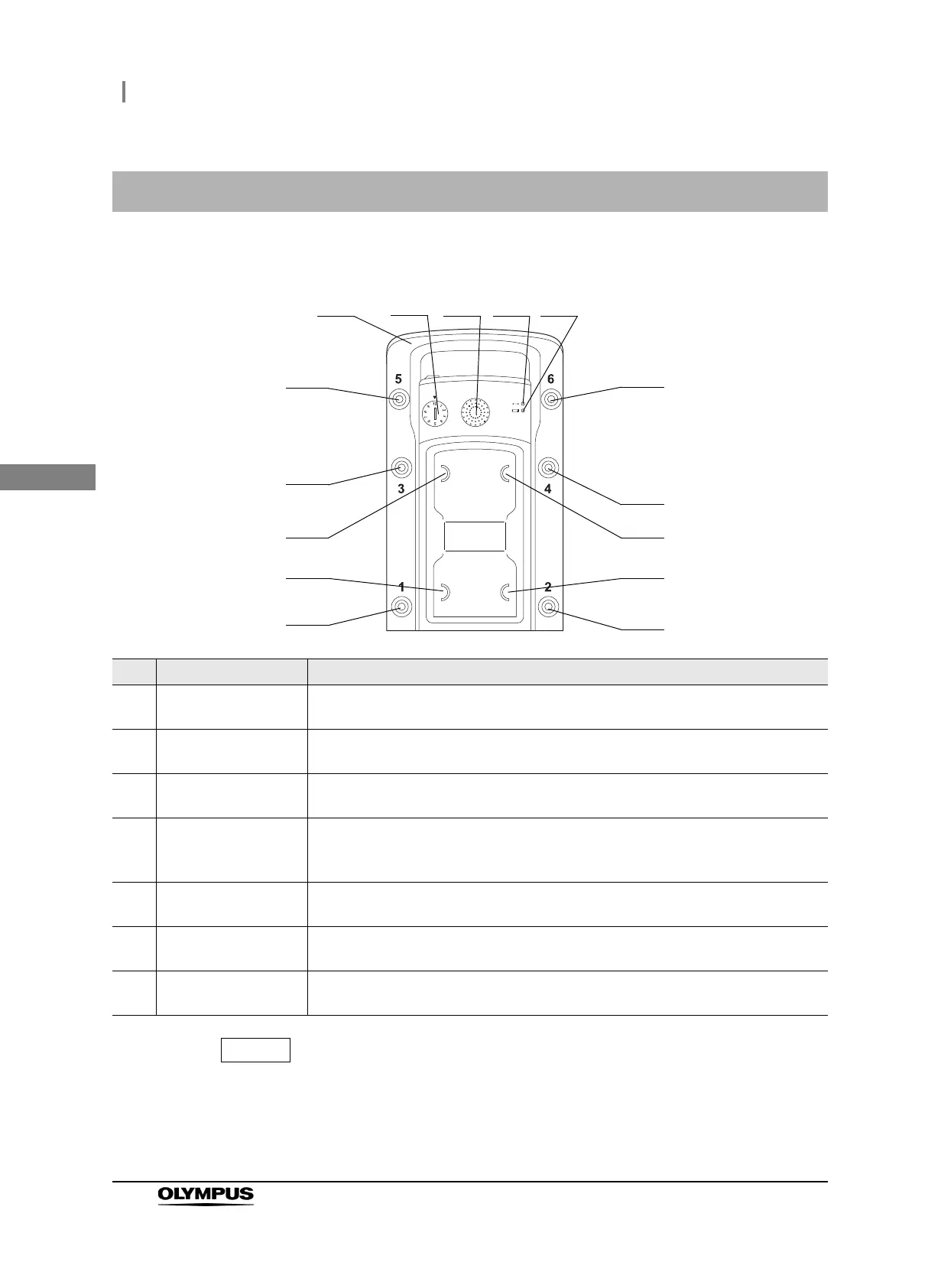
Upper surface
For the function assignment of the switches, refer to the instruction manual for the
surgical microscope.
2.2 Foot switch
No. Name Description
1 Handle To be held when carrying the foot switch. It can also be hooked on the foot switch
hanger when storing the foot switch.
2 Pairing indicator Indicates pairing with the combined wireless unit.
Refer to Section 3.6, “Pairing”.
3 Joystick Used to control the movement by the joystick on the foot switch of the surgical
microscope.
4 Communication status
indicator
The green LED lights when the communication status is good and flashes when it
deteriorates.
Refer to Section 5.2, “Wireless control of foot switch”.
5 Battery power indicator The amber LED lights or flashes according to the remaining battery power level.
Refer to Section 3.5, “Insertion of batteries into the foot switch”.
6 Foot switches 1 – 6 The functions of the surgical microscope can be assigned to these switches. The
function assignment is performed from the surgical microscope.
7 Foot switches A – D Used to control the focusing and zooming functions of the surgical microscope. The
functions of the four switches are assigned from the surgical microscope.
2
3
7 (A)
6 (6)
1
6 (4)
6 (2)
6 (5)
6 (3)
7 (B)
6 (1)
7 (C)
7 (D)
4 5