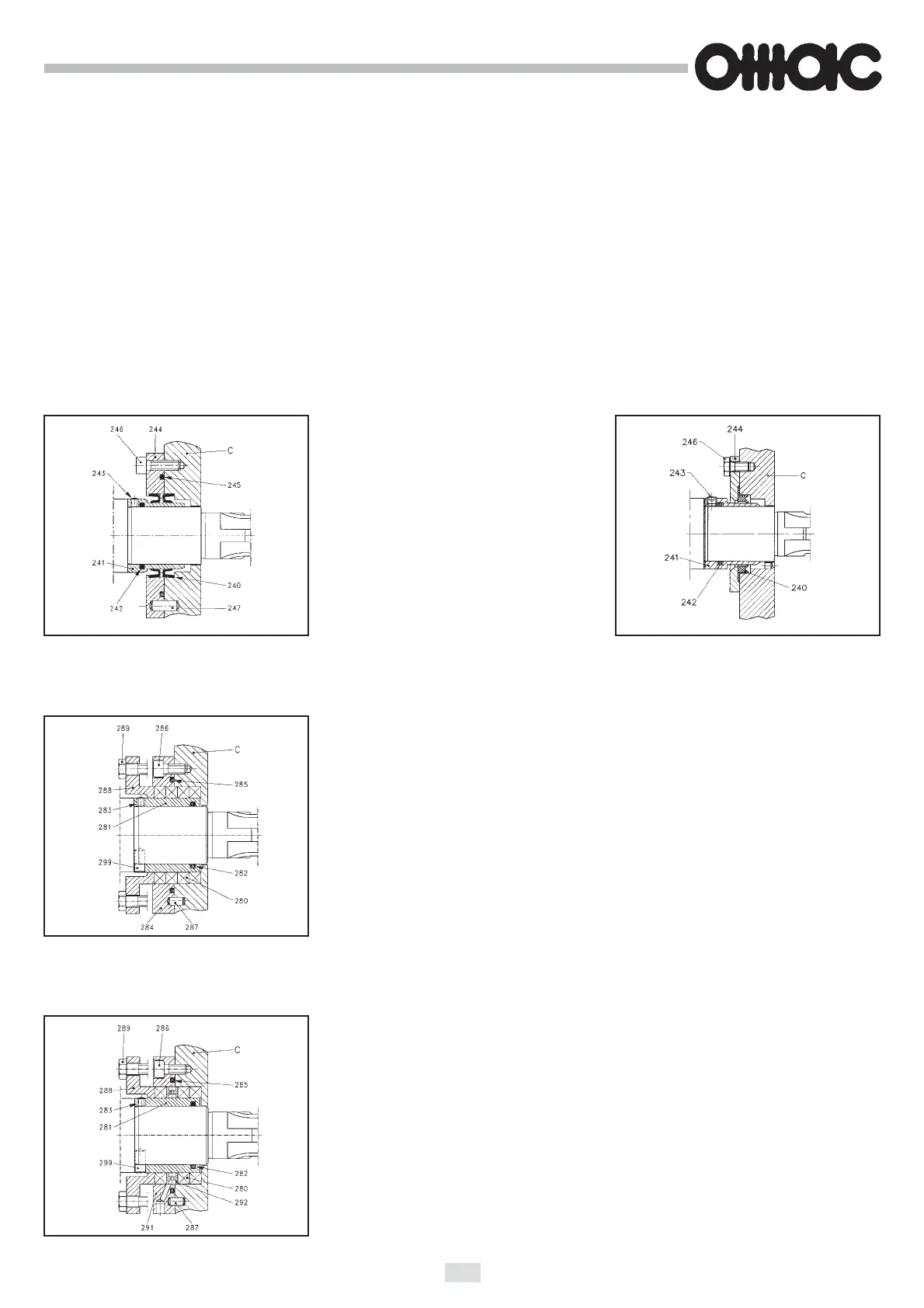
LIP SEAL
Pos. 242 - 245 = N.B.R. (viton) O-ring
Pos. 240 = "UM" viton rings (Fig. 27/a)
"UM" polymer S1 rings
(Fig. 27/b)
33
10. DRIVING SHAFT INVERSION - PUMP TYPE B5 - B6
1 - To invert the drive shaft position it's necessary to remove the shafts from bearing housing, as previously described.
IMPORTANT! (See fig. 20): Mark the rotors B, the bearing supports (75) and the axial adjustement spacers (11) in order
to re-set them rightly on the same shaft while re-assembling.
2 - Re-assemble the inverted shafts, each with the corresponding marked details on disassembly. The gears must mesh
with the same gear and tooth space, previously marked, in order to respect timing.
Being completely assembled, check clearances and rotor timing are included in tolerance table as per tab. 13.
11. SPARE PARTS CHOICE
1 - Seals for pump type B1 - B2 - B3 - B4 - B550
PACKING GLAND
Pos. 285 - 282 = N.B.R. (viton) O-ring
Pos. 280 = PTFE lubricated braid packing ring
PACKING GLAND WITH HYDRAULIC BARRIER
Pos. 292 = AISI 316 SS hydraulic ring for flushing of a liquid.
Fig. 27/a Code 0
Fig. 28 Code 1
Fig. 29 Code 2
Fig. 27/b Code 0