2.3 Electrical Installation
2.3.1 Power Connections
Caution: Do not connect power to your device until you have completed all
input and output connections. Failure to do so may result in injury!
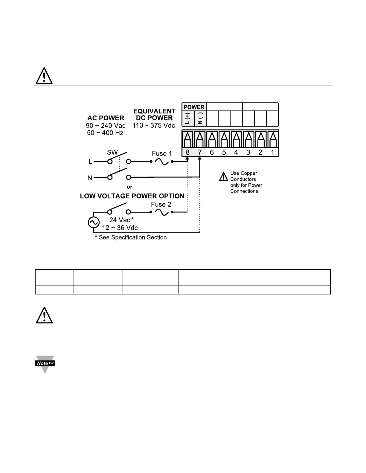
Connect the main power connections as shown in Figure 2.4.
Figure 2.4 Main Power Connections
Table 2.3 Fuse Requirements
FUSE Connector Output Type For 115Vac For 230Vac DC
FUSE 1 Power N/A 100 mA(T) 100 mA(T) 100 mA(T)
FUSE 2 Power N/A N/A N/A 400 mA(T)
For the low voltage power option, in order to maintain the same degree of
protection as the standard high voltage input power units (90 - 240 Vac),
always use a Safety Agency Approved DC or AC source with the same
Overvoltage Category and pollution degree as the standard AC unit
(90 - 240 Vac).
The Safety European Standard EN61010-1 for measurement, control,
and laboratory equipment requires that fuses must be specified based on
IEC127. This standard specifies for a Time-lag fuse, the letter code “T”.
The above recommended fuses are of the type IEC127-2-sheet III. Be
aware that there are significant differences between the requirements
listed in the UL 248-14/CSA 248.14 and the IEC 127 fuse standards. As a
result, no single fuse can carry all approval listings. A 1.0 Amp IEC fuse
is approximately equivalent to a 1.4 Amp UL/CSA fuse. It is advised to
consult the manufacturer’s data sheets for a cross-reference.
7
 Loading...