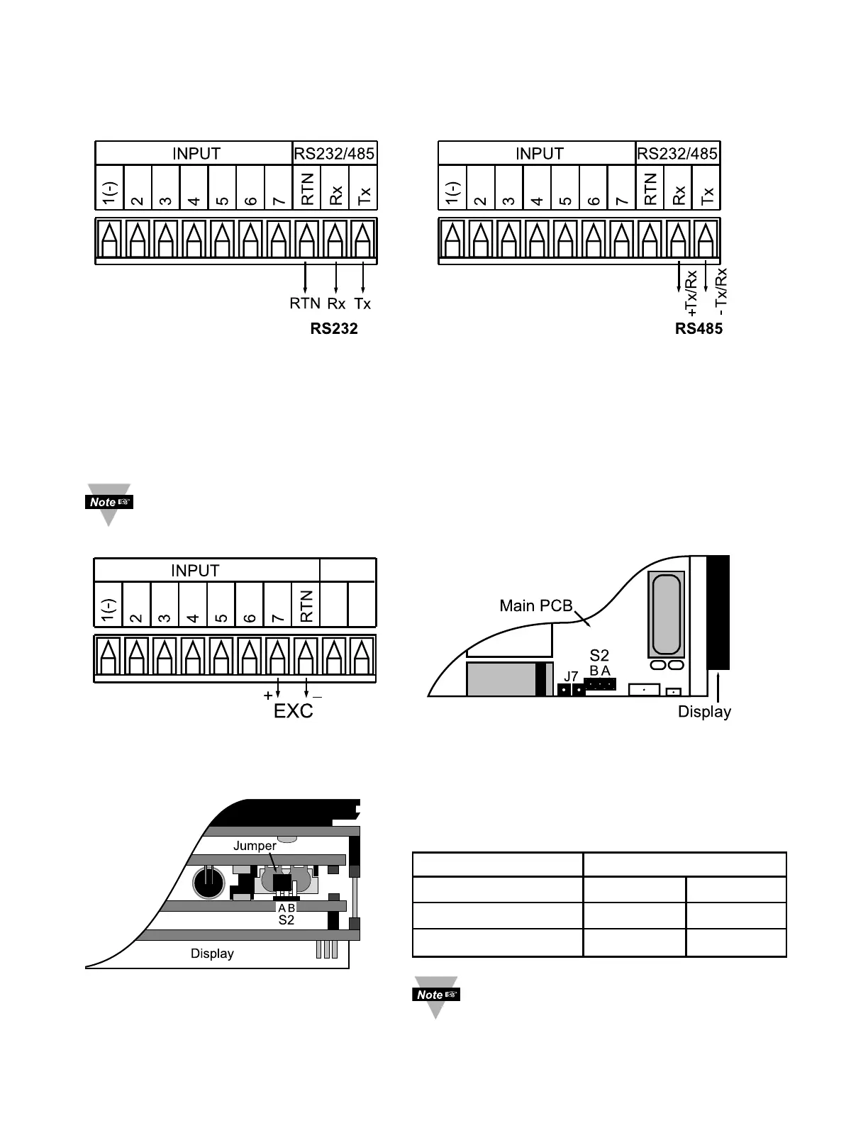
This device may have a programmable communication output. The RS-232 and
RS-485 Output Connection are shown below.
Figure 2.11
a) RS-232 Output Wiring Hookup b) RS-485 Output Wiring Hookup
This meter is capable of supplying 5 or 10 Vdc sensor excitation. The excitation
output connection and location of S2 pin selection jumper are shown below.
Excitation is not available if Serial Communication (-C24) or Ethernet
(-C4EI) or Low Voltage Power Supply
(-DC) options are installed.
Figure 2.12
a) Excitation Output b) Top View Location of S2
c) Top View Location of S2
on
1
/8 DIN Compact Unit
11
Install jumpers according to the table below.
Table 2.4 Jumper Connections
Excitation Output S2
AB
10 V Close Open
5 V Open Close
Factory default is 10 V.
 Loading...