EasyManuals Logo

Omega Engineering i Series User Manual

Omega Engineering i Series
56 pages
To Next Page IconTo Next Page
To Previous Page IconTo Previous Page
Page #14 background imageLoading...
Page #14 background image
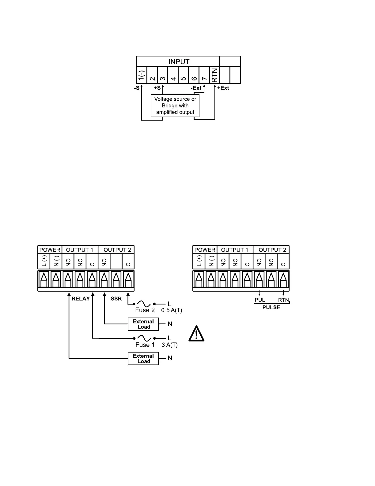
The figure below shows Voltage (bridge with amplified output) input with internal
excitation.
Figure 2.9 4-Wire Voltage Input (Bridge with Amplified Output)
with Internal Excitation
Where: +S: signal plus, -S: signal return, +Ext: excitation plus, -Ext: excitation return
+E: plus excitation sense, -E: minus excitation sense.
2.3.5 Wiring Outputs
This meter, if ordered with -AL Limit Alarm Option, has two, factory installed,
outputs. The SPDT Mechanical Relay, SPST Solid State Relay and Pulse Output
Connection are shown below.
Figure 2.10
a) Mechnical Relay and SSR b) Pulse Outputs
Outputs Wiring Hookup Wiring Hookup
Use copper conductors only
for power connections.
10

Table of Contents

Questions and Answers:

Question and Answer IconNeed help?

Do you have a question about the Omega Engineering i Series and is the answer not in the manual?

Omega Engineering i Series Specifications

General IconGeneral
BrandOmega Engineering
Modeli Series
CategoryMeasuring Instruments
LanguageEnglish

Related product manuals