Home
Omega Engineering
Measuring Instruments
i Series
Omega Engineering i Series User Manual
4
of 1
of 1 rating
56 pages
Give review
Manual
Specs
To Next Page
To Next Page
To Previous Page
To Previous Page
Loading...
16
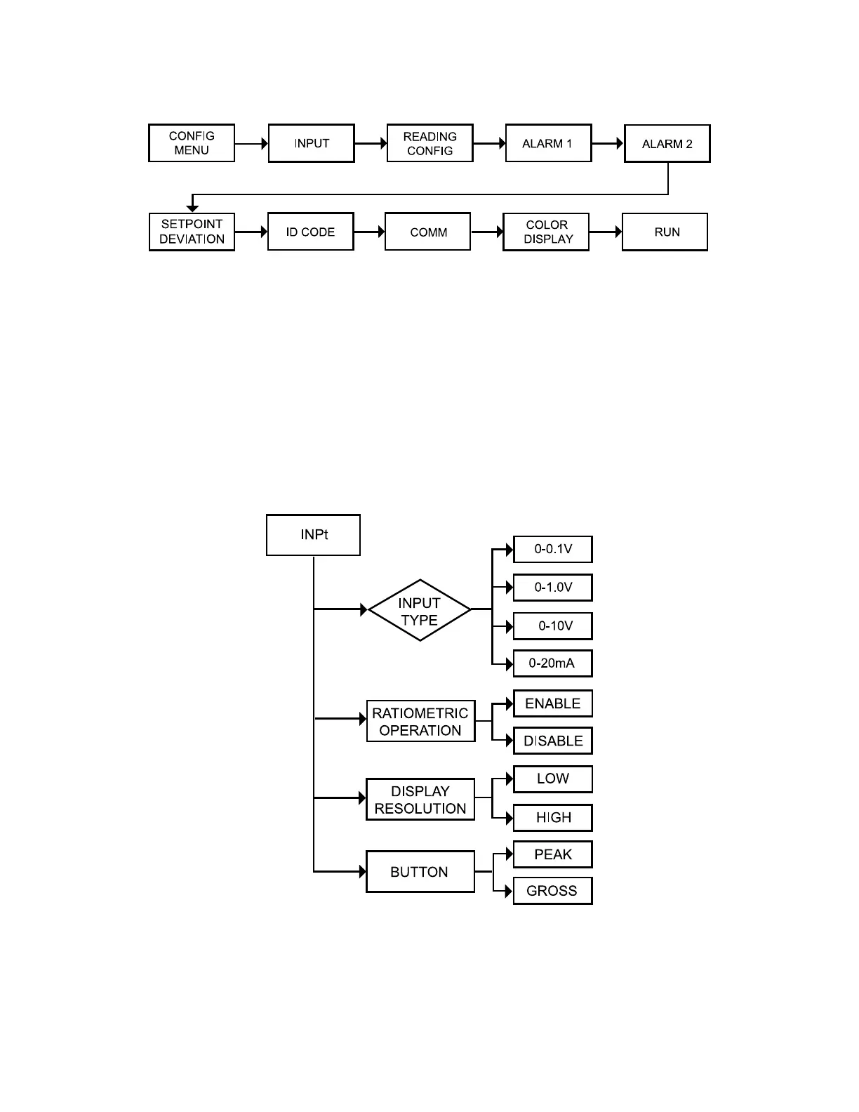
3.2.3 Configuration Menu
Figure 3.2 Flow Chart for Configuration Menu
Enter Configuration Menu:
Press
a
1)
Press
a
, if necessary
, until
CNFG
prompt appear
.
Press
d
2)
Display advance to
INPT
Input Menu.
Press
a
3)
Press and release
a
to scroll through all available menus of
Configuration section.
3.2.4 Input T
ype Menu
Figure 3.3 Flow Chart for Input T
ype Menu
19
21
Table of Contents
Table of Contents
3
Part 1: Introduction
6
Description
6
Safety Considerations
7
Before You Begin
8
Part 2: Setup
9
Front Panel
9
Rear Panel Connections
9
Figure 2.1 Front Panel Display
9
Figure 2.2 Rear Panel Power Connections
9
Table 2.1 Front Panel Display
9
Figure 2.3 Rear Panel Input Connections
10
Table 2.2 Rear Panel Connector
10
Electrical Installation
11
Power Connections
11
Figure 2.4 Main Power Connections
11
Table 2.3 Power Connections
11
Process Current
12
Process Voltage
12
Figure 2.5 Process Current Wiring Hookup
12
B) Process Voltage Without Sensor Excitation
12
Strain Gauge
13
B) 4-Wire Bridge Input with External Excitation
13
Figure 2.8 A) 6-Wire Voltage Input with Internal Excitation
13
B) 6-Wire Bridge Input with External Excitation
13
Wiring Outputs
14
Figure 2.9 4-Wire Voltage Input with Internal Excitation
14
Figure 2.10 A) Mechanical Relay and SSR Outputs Wiring Hookup
14
B) Pulse Output Wiring Hookup
14
Figure 2.11 A) RS-232 Output Wiring Hookup
15
B) RS-485 Output Wiring Hookup
15
Figure 2.12 A) Excitation Output
15
B) Top View Location of S2
15
C) Top View Location of S2 on
15
DIN Compact Unit
15
Table 2.4 Jumper Connections
15
Part 3: Operation: Configuration Mode
16
Introduction
16
Table 3.1 Button Function in Configuration Mode
16
Menu Configuration
17
Figure 3.1 Flow Chart for ID and Setpoints Menu
17
ID Number
18
Set Points Menu
19
Configuration Menu
20
Figure 3.2 Flow Chart for Configuration Menu
20
Figure 3.3 Flow Chart for Input Type Menu
20
Input Type Menu
20
Figure 3.4 Flow Chart for Reading Configuration Menu
22
Reading Configuration Menu
22
Input/Reading (Scale and Offset) Menu
25
Table 3.2 Conversion Table
26
Table 3.3 Input Resolution Multiplier
26
Alarm 1 Menu
29
Figure 3.5 Flow Chart for Alarm 1 Menu
29
Alarm 2 Menu
33
Figure 3.6 Flow Chart for Alarm 2 Menu
33
Figure 3.7 Flow Chart for Setpoint Deviation Menu
34
Setpoint Deviation Menu
34
Figure 3.8 Flow Chart for ID Code Menu
35
ID Code Menu
35
Communication Option Menu
37
Figure 3.9 Flow Chart for Communication Option Menu
37
Display Color Selection Menu
44
Figure 3.10 Flow Chart for Display Color Selection Menu
44
Part 4: Specifications
47
Table 5.1 Factory Preset Values
49
Part 5: Factory Preset Values
49
Ce Approval Information
51
4
Based on 1 rating
Ask a question
Give review
Questions and Answers:
Need help?
Do you have a question about the Omega Engineering i Series and is the answer not in the manual?
Ask a question
Omega Engineering i Series Specifications
General
Brand
Omega Engineering
Model
i Series
Category
Measuring Instruments
Language
English
Related product manuals
FMA-1600A Series
76 pages
Omega Engineering HX200
12 pages