Series Interface
6
Section 6.4 - Multiple Register Writes
When writing a dual register entity the lower order register should be used as the
requested ‘holding register’, with a request for minimum of 2 registers. The write
data is internally buffered and transferred to the database entry as a 32-bit value.
The access can be split into 2 consecutive single register writes. When the lower
(base) register is written the 16-bit entity is internally buffered BUT NO DATA
TRANSFER IS MADE TO THE DATABASE. The following single register write
must specify the next consecutive register address. The two least significant bytes
of the write request are combined with the previous write data and the entire 32-bit
entity is written to the database.
Attempts to write the two least significant bytes without first writing the two most
significant bytes will result in an error response.
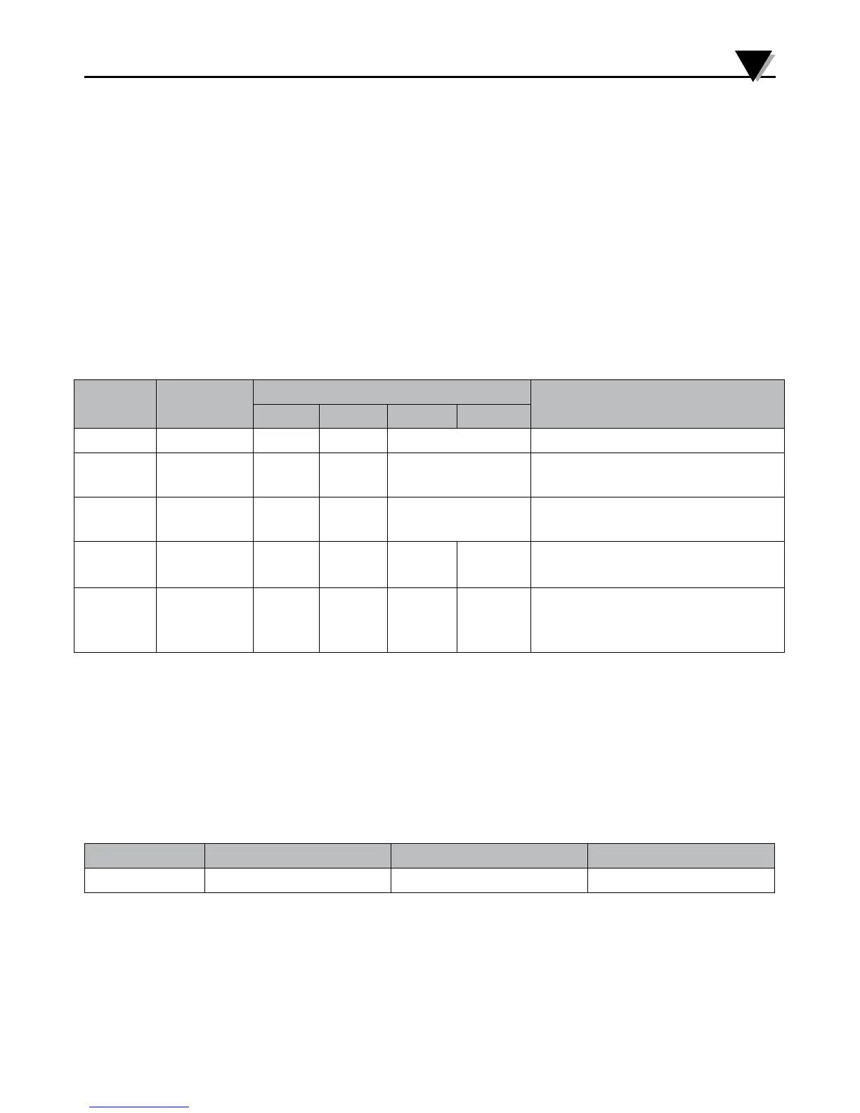
Data
Types
Number of
Registers
Byte
Description
0 1 2 3
Boolean 1 LSB N/A Zero= OFF, non-zero = ON
Byte,
Char
1 LSB N/A Entity contained in LSB of
register, Byte 0 ignored.
Int16,
uint16
1 MSB
0
LSB
1
N/A
2 3
Entity contained in MSB/LSB of
register. (dual register data)
Int32,
uint32
2 MSB B-1 B-2 LSB Requires 2 consecutive
registers, MSB transferred first
float 2 Sign+E
xp
Mantisa
MSB
B-1 Mantisa
LSB
IEEE formatted value con-
tained in 2 consecutive regis-
ters
Table 9 - Multiple Register Writes
Section 6.5 - Request Packet Sizes
Multiple consecutive registers may be accessed in a single transaction.
The DP606A and DP612A Modbus interface imposes a maximum of 72 bytes for the
total transaction. Allowing for the required framing, addressing and CRC results
in the following data size restrictions using the READ and WRITE MULTIPLE
functions.
Format Protocol Overhead Maximum Read data Maximum Write data
RTU 8 24 Registers 24 Registers
Table 10 - Packet Sizes
22
 Loading...