14
Getting Started (continued) Step Two
SENSOR OUTPUT TO LOCAL DISPLAY/CONTROLLER
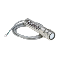
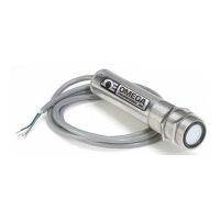
LVU500 series
outputs a 4-20 mA signal to a local display/controller or to remote devices such as PLCs,
SCADA, DCS or other displays/controllers. The 4-20 mA signal is set relative to the Sensor Height and Fill-
Height settings. These settings create an operational range that can be translated into a level reading in
defined units (i.e. inches, feet, gallons, meters, liters, etc.).
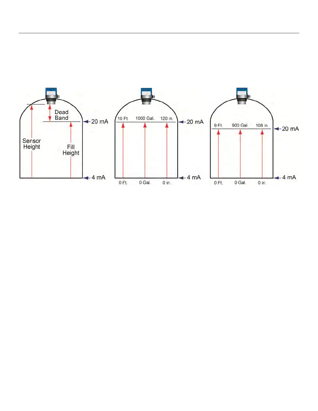
Tank A
Tank B
Tank C
In the Tank A example, the Sensor Height sets the 4mA to the bottom of the tank. Fill-Height sets the 20mA to
the top of the straight side of the tank.
In the Tank B example, the 4-20mA sensor range is correlated to actual units of level measurement. The
operational range now will have engineering values of 0 to 10 feet or 0 to 1000 gallons or 0 to 120 inches.
In the Tank C example, the 20mA setting was lowered by 1 foot, so the engineering values for the new shorter
operational ranges are either 0 to 9 feet, 0 to 900 gallons or 0 to 108 inches.
 Loading...