41
Appendix Section Seven
FACTORY SETTINGS
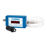
LVU500 series Sensor Height Fill-Height
LVU503 Series 118.1” (300 cm) 114.1” (290 cm)
LVU501 Series 59.1” (150 cm) 57.6” (146.2 cm)
USER SETTINGS
Fill out the chart below and keep as a record of your configuration.
Tank
Height = Fill-H =
Units
Inches Feet cm Meter
Display
Air Liquid
Safe
22mA 21 mA 20mA Hold Last 4mA
Rev mA
4mA @ Bottom 4mA at Top
Start-up
4mA 12mA 20mA 22mA
Relay(s)
Relay 1 (Blue) Relay 2 (Orange) Relay 3 (Yellow) Relay 4 (Purple)
ON
OFF
TROUBLESHOOTING
PROBLEM SOLUTION
Transmitter indicates a
current of 0 mA:
Check the wiring for an open circuit. An open circuit is the most common issue
with a 0 mA signal.
Transmitter jumps to a
current reading between
19 and 20 mA:
Check the installation of the transmitter. Bad installation fittings will cause
false signals near the top of the tank, which typically translates to a signal
between 19 and 20 mA. Also look for interference just below the transmitter. If
the transmitter is installed in a metal fitting, switch to a plastic fitting.
Transmitter indicates a
current over 23 mA:
Immediately check the wiring for a short circuit. The LVU500 series is current
limited to 22 mA. Anything above 23 mA indicates a short circuit.
 Loading...