15
Configuration Step Three
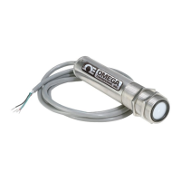
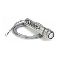
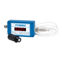
LVU500 series
can be configured before installation. The transmitter features non-volatile memory, so any
setting configured before installation will not be lost when the switch is powered down. To configure, follow the
steps below:
1. Install LVCN414-SW software
a. Go to omega.com/ftp and select the installer program.
b. Review how USB
®
Fob interfaces with LVU500 series and your computer.
2. Measure the Tank
a. Begin by measuring the key tank and fitting dimensions.
b. Include all settings for each relay.
c. Correct tank dimensions will result in accurate sensor measurement.
3. Sensor Configuration
a. Configures Number of Pumps, Pump/Valve Action, Pump/Valve Mode, Relay Fail-Safe,
Switch/Alarm Configuration, Switch Hysteresis/Dead Band, Loop Fail-Safe & Output at Empty for
the sensor.
4. Dimensional Entry
a. Distance Mode (default)
i. Basic information for operation (Sensor Height & Fill-Height).
ii. Relay activation settings.
5. Tank Level Confirmation
a. Confirm the values are accurate for the application.
6. Write to Unit
a. Uploads configuration into the sensor.
b. Access to a customer wiring diagram specific to the relay configuration.
 Loading...