21
Installation Step Four
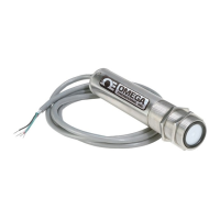
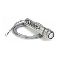
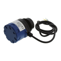
LVU500 series should always be mounted perpendicular to the liquid surface (use the provided FKM mounting
gasket for G threaded versions only). Make sure that the fitting and transmitter threads are not damaged or
worn. Always hand-tighten the transmitter within the fitting. Perform an installed leak test under normal
process conditions prior to system start up.
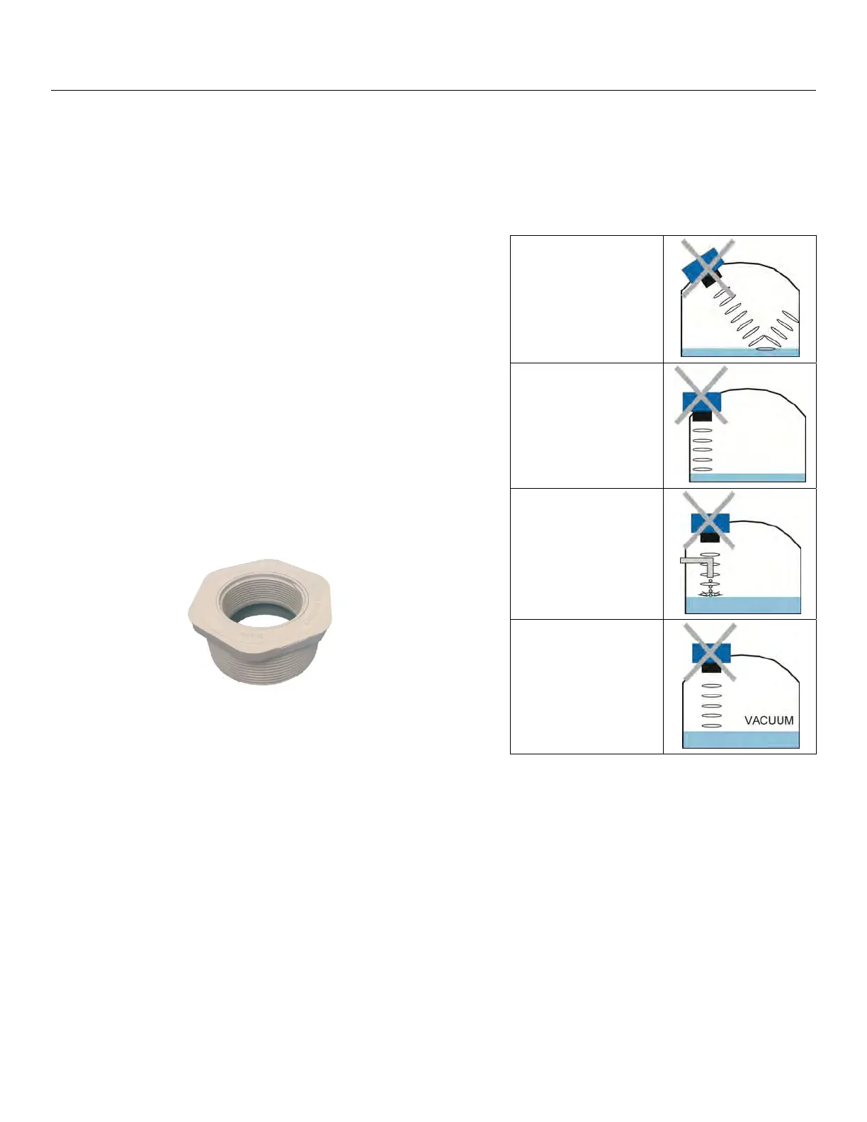
MOUNTING GUIDE
1. Do not mount at an angle
2. Liquid should never enter the dead band
3. Side Wall:
a. Mount at least 3” from the side wall
4. Do not mount where obstacles will intrude on sensor’s
beam width
5. Do not mount in a vacuum
6. Avoid mounting in the center of a dome top tank.
7. In cone bottom tank, position the sensor over the
deepest part of the tank.
Installation in existing fittings: If the existing fitting is
larger than the threads of the LVU500 series, select a
reducer bushing such as the LVU800-3N40 (3” thread x 2”
thread) or LVU800-4N80 (4” thread x 2” thread).
LVU800-3N40
Do not install at an
angle relative to the
liquid.
Do not install within
3” of tank sidewall.
Do not install with
objects in the
beam.
Do not install in
applications with
vacuum.
 Loading...