Using the Infrared Thermometer/Transmitter
3
3-2
3.2 How To Wire the Thermometer
3.2.1 OS550A Series Cable Connection
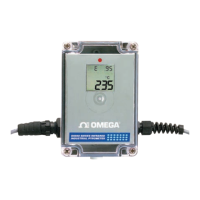
The OS550A Series thermometer comes with a built-in 4.5 m (15') sensor
cable and power/output cable. Plug in the two cables to the mating
connectors on the Enclosure. Power and output connections are made to the
cable via stripped wire ends located at the other end of the cable. The
power/output cable can be shortened or extended in the field if needed. See
table 3-1 below for wire Connection.
Note: Power Input and Analog output share the same common ground.
Table 3-1 Power/ Output Cable Connection
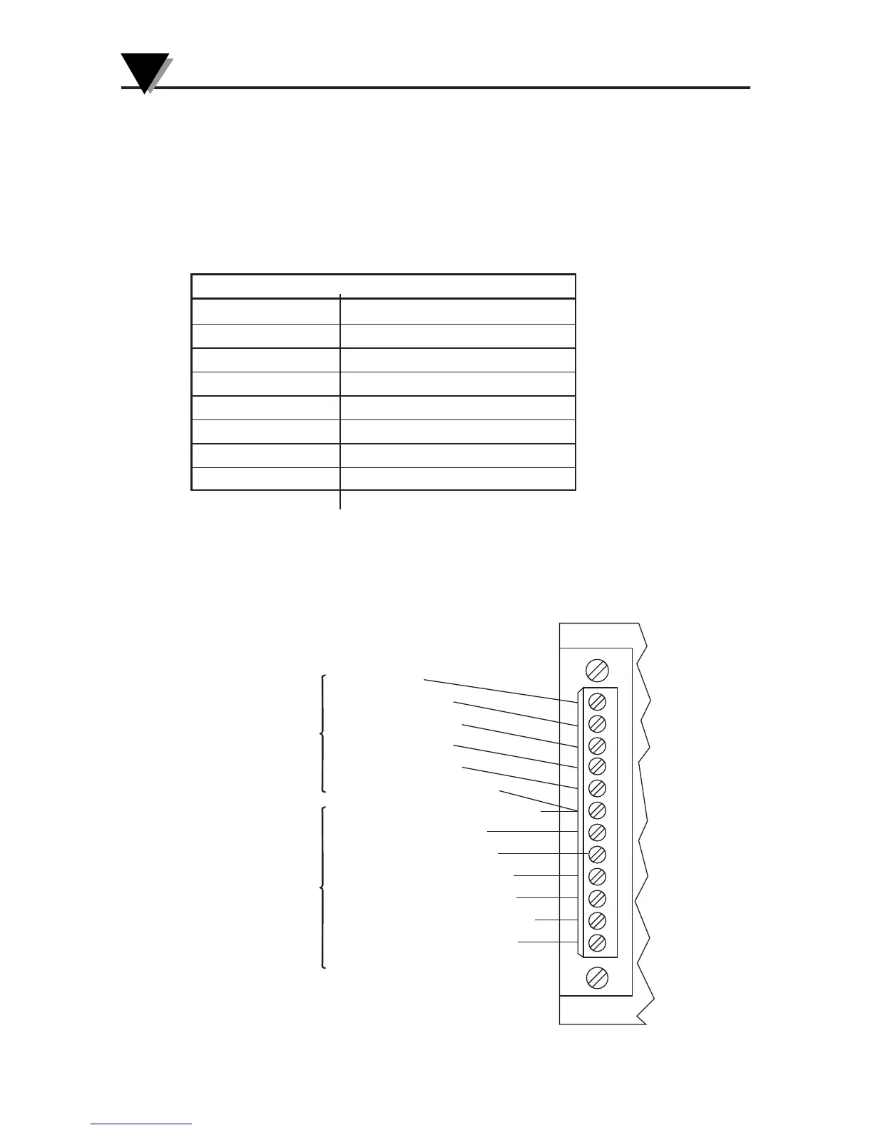
3.2.2 OS550-BB Series Terminal Block Wire Connections
Figure 3-2. OS550A-BB Wire Connection
Cable Wire Connection
Red + Power Input
Black – Power Input
White + Analog Output
Green – Analog Output
Yellow High Alarm Output
Blue Low Alarm Output
Orange No Connection
Shield Earth Ground
5
4
3
2
1
6
7
8
9
10
11
12
RED WIRE (+5V)
WHITE WIRE (CHAN 1)
GREEN WIRE (CHAN 2)
YELLOW WIRE (TAMB)
BLACK WIRE (GROUND)
SHIELD WIRE - SENSOR CABLE
SHIELD WIRE - POWER/OUTPUT CABLE
RED WIRE (+ POWER INPUT)
BLACK WIRE (– POWER INPUT)
WHITE WIRE (+ ANALOG OUTPUT)
GREEN WIRE (– ANALOG OUTPUT)
YELLOW WIRE (HIGH ALARM OUTPUT)
BLUE WIRE (LOW ALARM OUTPUT)
ORANGE - NO CONNECTION
SENSOR
CABLE
CONNECTION
POWER
OUTPUT/
CABLE
CONNECTION
 Loading...