LVS-7500 External System Operations Manual
LVS-7500 External System Operations Manual Page 66 of 129
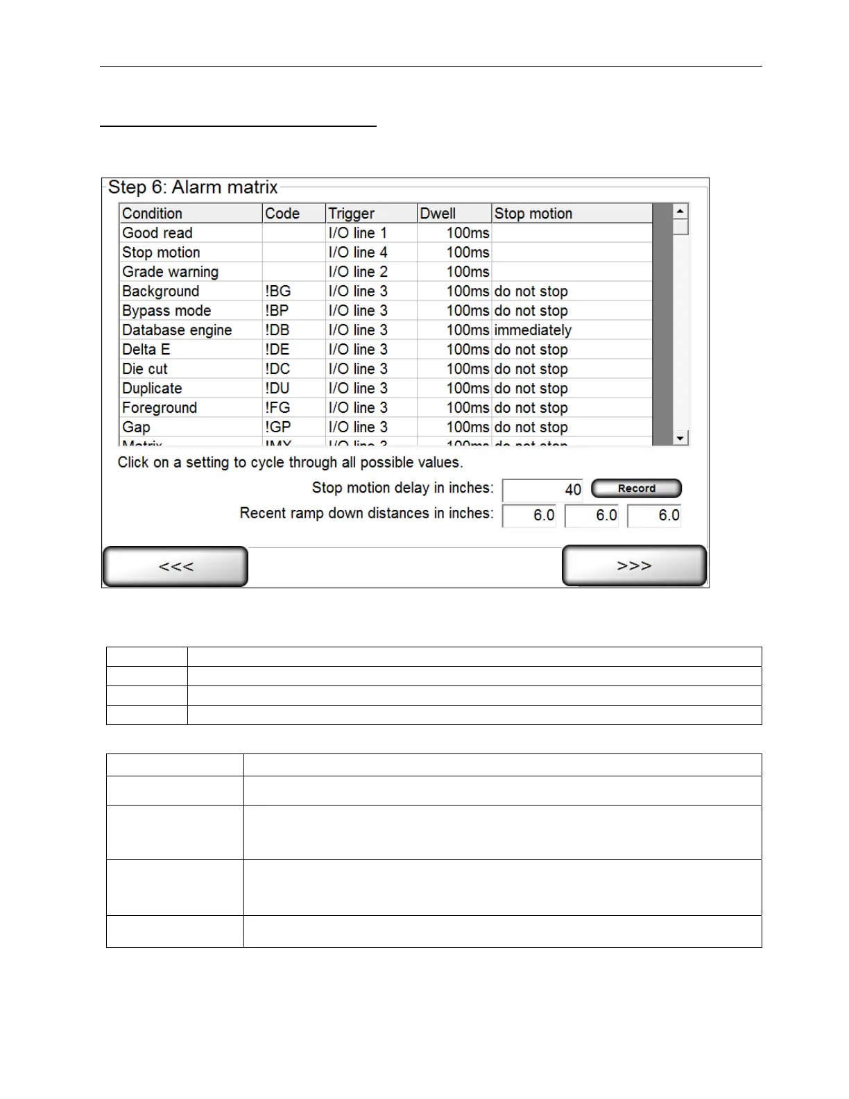
Alarm Matrix: Error Condition View
After all sectors have been established, you are prompted to determine an error condition. See the section below
entitled “Error Conditions” for more information.
Depending on the supplied hardware, the following relay outputs can be triggered by any of the listed error
conditions:
Line 1
Connected to the Green light, indicating a “good read”. It is not connected to a relay
Line 2
Connected to the Yellow light
Line 3
Connected to the Red light
Line 4
Connected to the Blue light
The 5 columns on this screen are listed below:
Column Description
Condition Lists the various error conditions that the system can detect.
Code
Lists the abbreviation of the error conditions detected by the system and used
throughout the final reports. See the Troubleshooting section for more
information on error codes.
Trigger
Lists any of the 4 Input/Output lines. Any listed error condition can be trained to
activate any I/O line by clicking on the appropriate row box; this will change the
path to another line. You can also choose “None”.
Dwell Lists the duration of the output signal. You can choose from “10 ms” to “hold”.
 Loading...