Function of Each Parameter
17
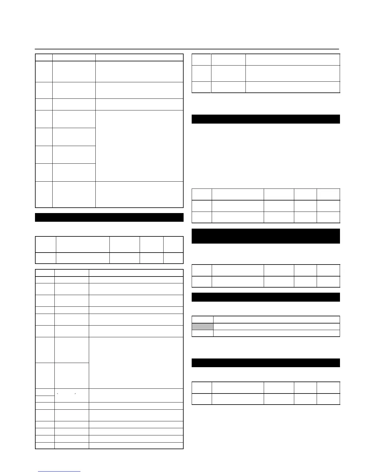
Value Function Description
15 Search command
(Searching starts
from preset frequen-
cy)
ON: Speed search (Searching starts from
the frequency specified by n03.)
16 Acceleration/Decel-
eration-prohibit com-
mand
ON: Acceleration/Deceleration is on hold
17 Local or remote
selection
ON: Local mode (operated with the Digital
Operator)
19 Emergency stop
fault (NO)
The Inverter stops according to the setting in
n04 for interruption mode selection when the
emergency stop input turns ON.
.
Note “STP” is displayed (lit with fault in-
put ON and flashes with alarm in-
put ON)
34 Up or down com-
mand
Up or down command (set in n39 only)
This setting overrides the n38 setting.
S4: Up command
S5: Down command
Multi-function Output Selection (n40)
Select the functions of multi-function output terminals.
Value Name Setting
range
Unit of
setting
Default
set-
tings
n40 Multi-function Output (MA/
MB and MC)
0 to 7, 10 to
17
1 1
Value Function Description
0 Fault output ON: Fault output
1 Operation in
progress
ON: Operation in progress
2 Frequency
detection
ON: Frequency detection
3 Idling ON: Idling
4 Frequency
detection 1
ON: Output frequency y frequency detection
level (n58)
5 Frequency
detection 2
ON: Output frequency x frequency detection
level (n58)
6 Overtorque
being monitored
(NO-contact
output)
Output if any of the following parameter
conditions is satisfied.
• Overtorque detection function selection (n59)
• Overtorque detection level (n60)
7 Overtorque
being monitored
(NC-contact
output)
10 Alarm output ON: Alarm being detected (Nonfatal error)
11 Base block in
progress
ON: Base block in progress
12 RUN mode ON: Local mode
13 Inverter ready ON: Inverter ready to operate
14 Fault retry ON: Fault retry
Value Function Description
15 UV in progress ON: Undervoltage being monitored (main circuit
undervoltage UV or UV1 detected)
16 Rotating in
reverse
direction
ON: Rotating in reverse direction
17 Speed search
in progress
ON: Speed search in progress
Note: Use “operation in progress” or “frequency detection 1/2”
for the timing of the external brake.
Gain and Bias Settings (n41 and n42)
Set the input characteristics of analog frequency references in
n41 (for the frequency reference gain) and n42 (for the frequen-
cy reference bias).
Set the frequency of maximum analog input (10 V or 20 mA) in
n41 as percentage based on the maximum frequency as 100%.
Set the frequency of minimum analog input (0 V, 0 mA, or 4 mA)
in n42 as percentage based on the maximum frequency as
100%.
Value Name Setting
range
Unit of
setting
Default
settings
n41 Frequency Reference
Gain
0 to 255 1% 100
n42 Frequency Reference
Bias
–99 to 99 1% 0
Analog Frequency Reference Filter Time Setting
(n43)
The digital filter with a first-order lag can be set for analog fre-
quency references to be input.
Value Name Setting
range
Unit of
setting
Default
settings
n43 Analog Frequency Refer-
ence Filter Time
0.00 to 2.00 0.01 s 0.10
Analog Monitor Output Setting (n44)
Set a monitored item for analog monitor output.
Value Description
0 Output frequency (Reference: 10 V at max. frequency)
1 Output current (Reference: 10 V with rated output current)
Note: The values in parentheses are applicable when n45 is
set to 1.00.
Analog Monitor Output Gain Setting (n45)
Set the output characteristics of analog monitor output.
Value Name Setting
range
Unit of
setting
Default
settings
n45 Analog Monitor Output
Gain
0.00 to 2.00 0.01 1.00