EasyManua.ls Logo

Omron 3G3JV User Manual

Omron 3G3JV
48 pages
To Next Page IconTo Next Page
Page #1 background imageLoading...
Page #1 background image
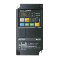
Simple, Compact Inverters
3G3JV
Series
Cat.No.I905-E1-05
Printed in Japan
0204-1M
OMRON Corporation
FA Systems Division H.Q.
66 Matsumoto
Mishima-city, Shizuoka 411-8511
Japan
Tel:(81)55-977-9181
Fax:(81)55-977-9045
Authorized Distributor:
Note: Specifications subject to change without notice.
Regional Headquarters
OMRON EUROPE B.V.
Wegalaan 67-69, NL-2132 JD Hoofddorp
The Netherlands
Tel:(31)2356-81-300/Fax:(31)2356-81-388
OMRON ELECTRONICS LLC
1 East Commerce Drive, Schaumburg, IL 60173 U.S.A.
Tel:(1)847-843-7900/Fax:(1)847-843-8568
OMRON IDM Controls
9510 North Houston, Tx. 77088 U.S.A.
Tel: (1)800-395-4106/Fax: (1)713-849-4666
OMRON ASIA PACIFIC PTE. LTD.
83 Clemenceau Avenue, #11-01, UE Square,
Singapore 239920
Tel:(65)6835-3011/Fax:(65)6835-2711
Note: Do not use this document to operate the Unit.
Question and Answer IconNeed help?

Do you have a question about the Omron 3G3JV and is the answer not in the manual?

Omron 3G3JV Specifications

General IconGeneral
Series3G3JV
Output Frequency0.1 to 400 Hz
Control MethodV/F Control
Operating Temperature-10 to 50°C
Altitude1000 m or less
TypeInverter
Protection FunctionsOvercurrent, Overvoltage, Undervoltage, Overheat
Braking UnitBuilt-in
Frequency Range0.1 to 400 Hz
Power Range0.1 kW to 2.2 kW
CommunicationRS-485 (Modbus RTU)
Storage Temperature-20 to 60°C

Summary

3G3JV Series: Compact, Easy Operation & Versatile Functions

List of Parameters: Core Settings (n01-n32)

Initialization, Modes, Frequency, and Protection

Parameters for setup, operation selection, frequency control, and motor protection.

Specifications: Electrical and Performance Data

200-V AC Model Specifications

Details rated voltage, capacity, heat radiation, and weight for 200-V models.

Terminal Block Layout and Connections

Main and Control Circuit Terminals

Diagrams and descriptions of main and control circuit terminal connections.

Standard Connections: Wiring Diagrams

Overall Wiring Diagram

Illustrates power supply, reactor, inverter, motor, and control signal connections.

Protective and Diagnostic Functions: Faults

Fatal Error Displays and Causes

Lists fault codes like OC, OV, UV, OH and their probable causes and remedies.

More Faults and Their Solutions

Digital Operator and Communication Faults

Protective and Diagnostic Functions: Warnings

Warning Displays and Causes

Lists warnings like UV, OV, OH, CAL, OL3 and their probable causes and remedies.

Sequence, Base Block, and Cooling Fan Warnings

Inverter Models and Product Code Explanation

Warranty and Application Considerations

Related product manuals