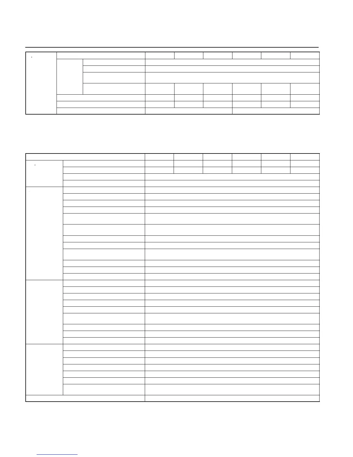
Model 3G3JV- A4002 A4004 A4007 A4015 A4022 A4037
Rated voltage and frequency 3-phase 380 to 460 V AC at 50/60 Hz
mo
s
supply
Allowable voltage fluctuation –15% to 10%
Allowable frequency
fluctuation
±5%
Input power supply capacity
(kVA) (see note 1)
1.3 1.9 3.6 5.1 5.9 9.1
Heat radiation (W) (see note 2) 23.1 30.1 54.9 75.7 83.0 117.9
Weight (kg) 1.0 1.1 1.5 1.5 1.5 2.1
Cooling method Natural cooling Cooling fan
Note: 1. The power supply capacity, is the capacity when the Inverter is operating at its rated output. The value will vary with the
impedance at the input power supply side. (Because the power factor of the input power supply changes, the power factor
will improve if an AC reactor is inserted.) The ratio with the rated current of the motor used and the rated output current of
the Inverter will vary.
2. The “heat radiation” is the power consumed in the Inverter when it is operating at its rated output.
Max. applicable motor capacity (kW) 0.2 0.4 0.75 1.5 2.2 3.7
Output
Rated output capacity (kW) 0.9 1.4 2.6 3.7 4.2 6.6
specifications
Rated output current (A) 1.2 1.8 3.4 4.8 5.5 8.6
Rated output voltage (V) 3-phase 380 to 460 V AC (according to the input voltage)
Max. output frequency 400 Hz parameter setting
Control
Harmonic-current countermeasures DC reactor (option) connection possible
characteristics
Control method Sine wave PWM (V/f control)
Carrier frequency 2.5 to 10.0 kHz (in vector control)
Frequency control range 0.1 to 400 Hz
Frequency precision (temperature
characteristics)
Digital commands: ±0.01% (–10°C to 50°C)
Analog commands: ±0.5% (25°C ± 10°C)
Frequency setting resolution Digital commands: 0.1 Hz (less than 100 Hz) and 1 Hz (100 Hz or over)
Analog commands: 0.06 Hz/60 Hz (equivalent to 1/1000)
Output frequency resolution 0.01 Hz (calculated resolution)
Overload capacity 150% of rated output current for 1 min
External frequency set signal Selectable with FREQ adjuster: 0 to 10 V DC (20 kΩ), 4 to 20 mA (250 Ω), and 0 to 20 mA
(250 Ω)
Acceleration/deceleration time 0.0 to 999 s (Independent acceleration and deceleration time settings)
Braking torque Approx. 20%
Voltage/frequency characteristics Set a user V/f pattern
Protective
Motor protection Protection by electronic thermal
functions
Instantaneous overcurrent protection Stops at approx. 250% of rated output current
Overload protection Stops in 1 min at approximately 150% of rated output current
Overvoltage protection Stops when main-circuit DC voltage is approximately 820 V
Undervoltage protection Stops when main-circuit DC voltage is approximately 400 V
Momentary power interruption
compensation (selection)
Stops for 15 ms or more. By setting the Inverter to momentary power interruption mode,
operation can be continued if power is restored within approximately 0.5 s.
Cooling fin overheating Detects at 110°C ± 10°C
Grounding protection Protection at rated output current level
Charge indicator (RUN indicator) Lit when the main circuit DC voltage is approximately 50 V or less.
Environment
Location Indoors (with no corrosive gas, oil spray, or metallic dust)
Ambient temperature Operating: –10°C to 50°C
Ambient humidity Operating: 95% max. (with no condensation)
Ambient temperature –20°C to 60°C
Altitude 1,000 m max.
Insulation resistance 5 MΩ min. (Do not carry out any insulation resistance or withstand voltage tests)
Vibration resistance 9.8 m/s
2
max. between 10 to 20 Hz
2.0 m/s
2
max. between 20 and 50 Hz
Degree of protection Panel-mounting models: Conforms to IP20