6
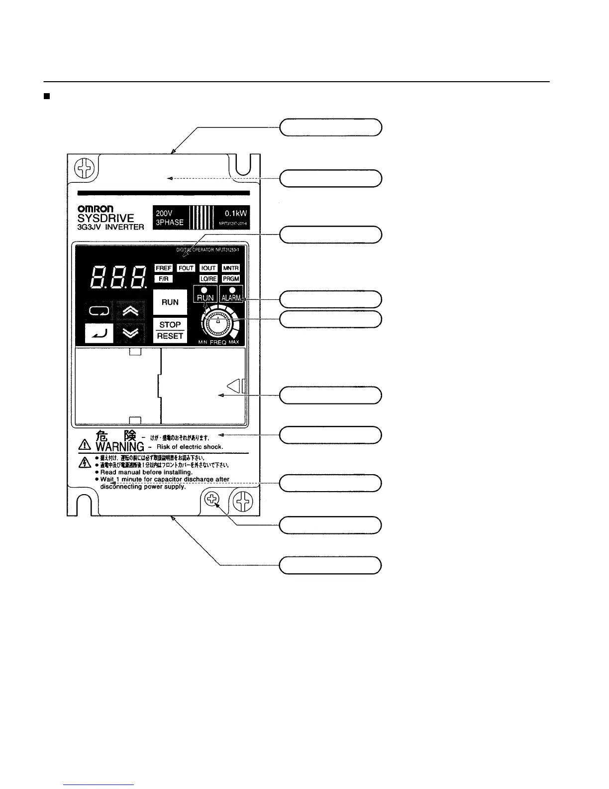
Panel
Upper terminal block:
A terminal block on the input side of the main circuit.
Top protection cover:
Remove this cover when wiring the upper terminal block.
Digital Operator:
Used to set parameters, perform various
monitoring, and start and stop the Inverter.
ALARM indicator:
RUN indicator:
Displays the operating status of the Inverter.
Alarm (Red): Lights when an error occurs. Flashes when a warning
occurs.
RUN (Green): Flashes when no RUN command is input during normal
status. Lights when a RUN command is input during normal status.
Optional cover:
Remove this cover when setting the input method selector.
Front cover:
Remove this cover when wiring the upper or lower terminal block.
Front cover mounting screw:
Bottom protection cover:
Remove this cover when wiring the lower terminal blocks.
Lower terminal blocks:
A terminal block on the output side of the main
circuit and a terminal block for the control circuit.
A screw for fixing the front cover.
Nomenclature