25
主回路
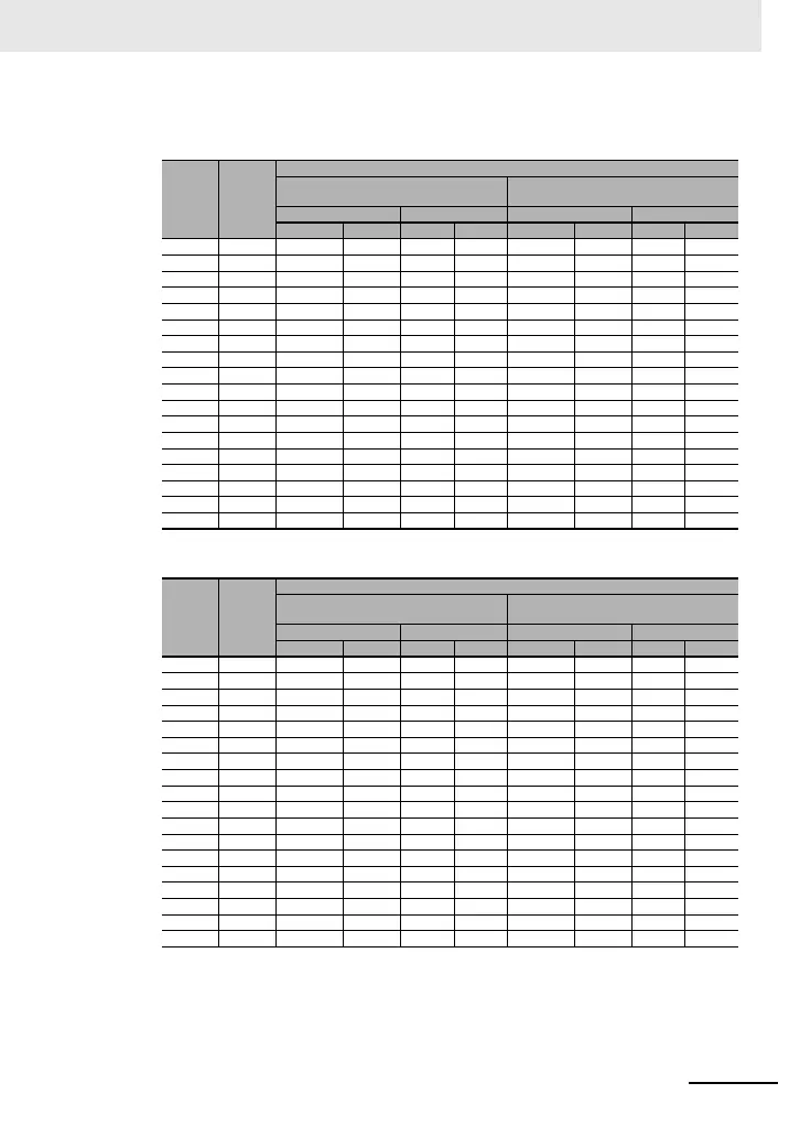
400V 級
• インバータ ND 定格設定時
• インバータ LD/VLD 定格設定時
(注)1.表に記載した形式は選定例です。ご使用の際は、表の定格電流を元に、電源回路の短絡電流や関連法規などを考
慮の上、適切な遮断容量、感度電流を持つ機種を選定ください。
2. 適用モータ容量は、標準モータ 4 極の 60Hz400Vac(400V 級)を使用する場合の選定例です。
3. 電磁接触器を AC-1 級でご使用の場合の電気的耐久性は、50 万回ですが、モータ駆動中の緊急停止は 25 回と
なります。
4. モータ駆動中の緊急停止あるいは商用運転がある場合のモータ側の電磁接触器は、モータの定格電流に対して
AC-3 級で選定してください。
5. インバータの定格容量がモータ容量よりも大きい場合は、インバータ形式を元に選定してください。
形式
3G3RX2
適用
モータ
(kW)
適用器具(入力電圧 400 〜 440V)
力率改善リアクトルなし
力率改善リアクトル
(形 3G3AX-AL または形 3G3AX-DL)
あり
漏電遮断器(ELB) 電磁接触器(MC) 漏電遮断器(ELB) 電磁接触器(MC)
形式例 定格電流 AC-1 AC-3 形式例 定格電流 AC-1 AC-3
A4007 0.75 EX50C 5 HS8 HS8 EX50C 5 HS8 HS8
A4015 1.5 EX50C 10 HS8 HS8 EX50C 5 HS8 HS8
A4022 2.2 EX50C 10 HS8 HS8 EX50C 10 HS8 HS8
A4037 3.7 EXK50-C 15 HS8 HS10 EX50C 10 HS8 HS8
A4055 5.5 EXK50-C 20 HS8 HS20 EXK50-C 15 HS8 HS20
A4075 7.5 EXK50-C 30 HS8 HS25 EXK50-C 20 HS8 HS20
A4110 11 EXK50-C 40 HS20 HS35 EXK50-C 30 HS8 HS25
A4150 15 EXK50-C 50 HS25 HS50 EXK50-C 40 HS20 HS35
A4185 18.5 EXK100-C 75 HS35 HS50 EXK50-C 50 HS20 HS35
A4220 22 EXK100-C 75 HS50 H65C EXK60-C 60 HS35 HS50
A4300 30 EXK100-C 100 HS50 H80C EXK100-C 75 HS50 H65C
A4370 37 RXK125-S 125 H80C H100C EXK100-C 100 HS50 H65C
A4450 45 EXK225 150 H80C H125C RXK125-S 125 H65C H80C
A4550 55 EXK225 200 H100C H125C EXK225 150 H80C H100C
B4750 75 RXK250-S 250 H150C H200C EXK225 200 H100C H125C
B4900 90 EX400 300 H200C H250C EXK225 225 H125C H150C
B411K 110 EX400 400 H200C H300C EX400 300 H150C H250C
B413K 132 EX600B 500 H250C H300C EX400 350 H200C H250C
形式
3G3RX2
適用
モータ
(kW)
適用器具(入力電圧 400 〜 440V)
力率改善リアクトルなし
力率改善リアクトル
(形 3G3AX-AL または形 3G3AX-DL)あり
漏電遮断器(ELB) 電磁接触器(MC) 漏電遮断器(ELB) 電磁接触器(MC)
形式例 定格電流 AC-1 AC-3 形式例 定格電流 AC-1 AC-3
A4007 1.5 EX50C 10 HS8 HS8 EX50C 5 HS8 HS8
A4015 2.2 EX50C 10 HS8 HS8 EX50C 10 HS8 HS8
A4022 3.7 EXK50-C 15 HS8 HS10 EX50C 10 HS8 HS8
A4037 5.5 EXK50-C 20 HS8 HS20 EXK50-C 15 HS8 HS20
A4055 7.5 EXK50-C 30 HS8 HS25 EXK50-C 20 HS8 HS20
A4075 11 EXK50-C 40 HS20 HS35 EXK50-C 30 HS8 HS25
A4110 15 EXK50-C 50 HS25 HS50 EXK50-C 40 HS20 HS35
A4150 18.5 EXK100-C 75 HS35 HS50 EXK50-C 50 HS20 HS35
A4185 22 EXK100-C 75 HS50 H65C EXK60-C 60 HS35 HS50
A4220 30 EXK100-C 100 HS50 H80C EXK100-C 75 HS50 H65C
A4300 37 RXK125-S 125 H80C H100C EXK100-C 100 HS50 H65C
A4370 45 EXK225 150 H80C H125C RXK125-S 125 H65C H80C
A4450 55 EXK225 200 H100C H125C EXK225 150 H80C H100C
A4550 75 EX400 250 H150C H200C EXK225 200 H100C H125C
B4750 90 EX400 300 H200C H250C EXK225 225 H125C H150C
B4900 110 EX400 400 H200C H300C EX400 300 H150C H250C
B411K 132 EX600B 500 H250C H300C EX400 350 H200C H250C
B413K 160 EX600B 600 H400C H400C EX400 400 H250C H300C
 Loading...


