1 Preparation
1-3 Name of each part
BN50T/BN75T/BN100T/BN150T/BN220T/BN300T
1-6
<BN220T/BN300T>
A. AC Input cable
B. AC Input overcurrent protection switch
C. Grounding terminal (M4 screw)
D. RS-232C port
E. USB port
F. Remote ON/OFF port
G. Option slot
H. Power supply output receptacle A
I. Power supply output receptacle B
J. Power supply output receptacle C
K. Cooling fan
BN220T
Use Copper Conductor Only.
Refer to the instruction manual
for the tightening torque.
入力サージ
保護GND
K
H
I
J
A
C
B
F
E
D
G
Left side: ON, right side: OFF
1 Preparation
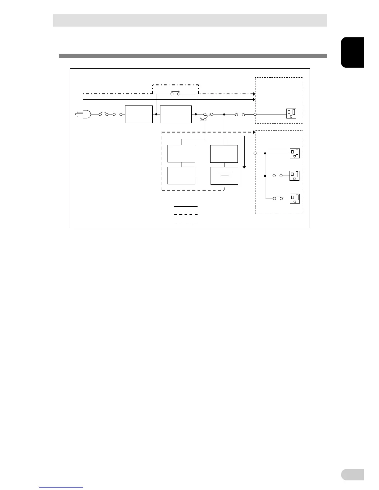
1-4 Diagram of the Input/output circuit block
BN50T/BN75T/BN100T/BN150T/BN220T/BN300T
1
1-7
1-4 Diagram of the Input/output circuit block
Charger
Batter
DC-DC
converter
Inverter
AC100V input
Input overcurrent protection
Noise filter
Line mode
Battery mode
Bypass mode
AVR transforme
BN50T/BN75T:
without output receptacle
control
BN100T/BN150T/BN220T/
BN300T:
without output receptacle control
Output group A
Output group B
Output group C
Power supply output receptacles