6 Using the contact signal functions
6-1 Contact signal functions
BN50T/BN75T/BN100T/BN150T/BN220T/BN300T
6
6-1
6 Using the contact signal functions
6-1 Contact signal functions
You can develop your unique system based on the following specifications to automate the
process at a power failure.
You can perform power-failure processing by allowing the system to detect the backup
signal and also perform system shutdown processing by allowing the system to detect the
Low battery level signal.
Also, by inputting the backup stop signal from the system, you can stop the UPS with a
sufficient battery level to prepare for the next occurrence of a power failure.
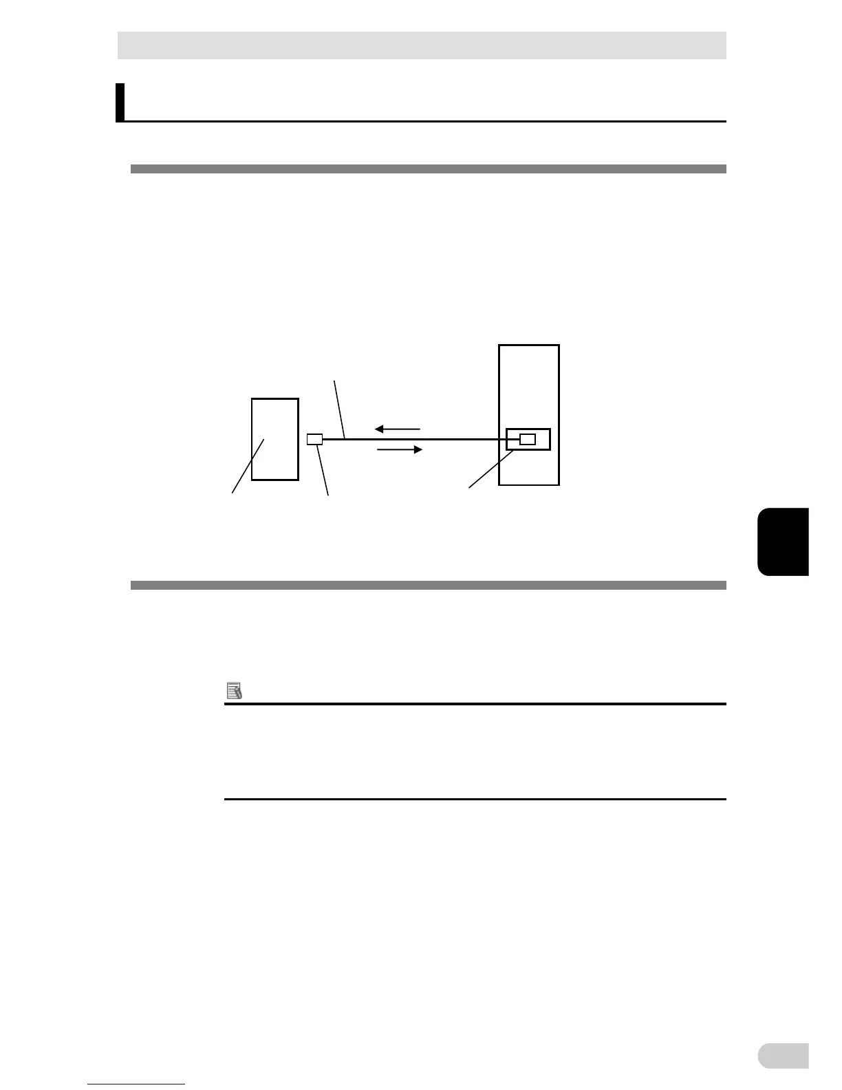
PC
Signals such as BU
UPS
Connection cable
BUC26
D-sub9pin
OS standard
UPS service
Contact signal card
SC07
Signals such as BS
COM
port
6-2 SC07 Contact signal card specifications
An additional contact signal card can be installed in the contact signal input/output slot on
the back of the UPS.
- Contact signal card (model number: SC07), sold separately
Note: Only remote ON/OFF signal can be at the remote ON/OFF connector without the contact
signal card.
Additional Information
A relay output type contact signal card (model number: SC08) is available for sep-
arate purchase.
It can be loaded into the option slot on the back of the UPS.
Visit our website for more details.
(URL: http://www.omron.co.jp/ese/)