3 Check and start operation
3-1 The name and function for the operation and display
BN50T/BN75T/BN100T/BN150T/BN220T/BN300T
3-1
3
3 Check and start operation
3-1 The name and function for the operation and
display
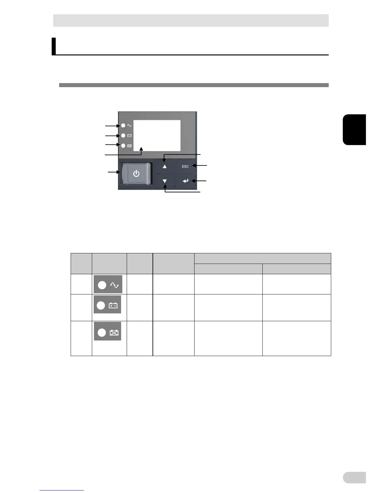
3-1-1 Name of each part
< Enlarged view of the operation panel>
A
B
C
E
F
H
I
G
D
: “Power supply output” LED E: “Power” switch
B: “Battery mode” LED F: “Up” switch
C: “Battery replacement” LED G: “Down” switch
D: Liquid Cell Display H: “ESC” switch
I: “Enter” switch
3-1-2 The meaning of each LED
Sign of
the figure
LED Color Name
Status
Lit. Not lit.
A
Green “Power supply
output” LED
The power supply output is
ON.
The power supply output is
OFF.
B
Orange “Battery mode”
LED
Backup is operating. This
status is called “Battery
Mode”.
Backup is not operating.
C
Red “Battery
replacement”
LED
Battery replacement is neces-
sary due to the battery deterio-
ration, the end of battery life, or
the end of UPS life.
Battery replacement is not
necessary.