6 Using the contact signal functions
6-2 SC07 Contact signal card specifications
BN50T/BN75T/BN100T/BN150T/BN220T/BN300T
6-2
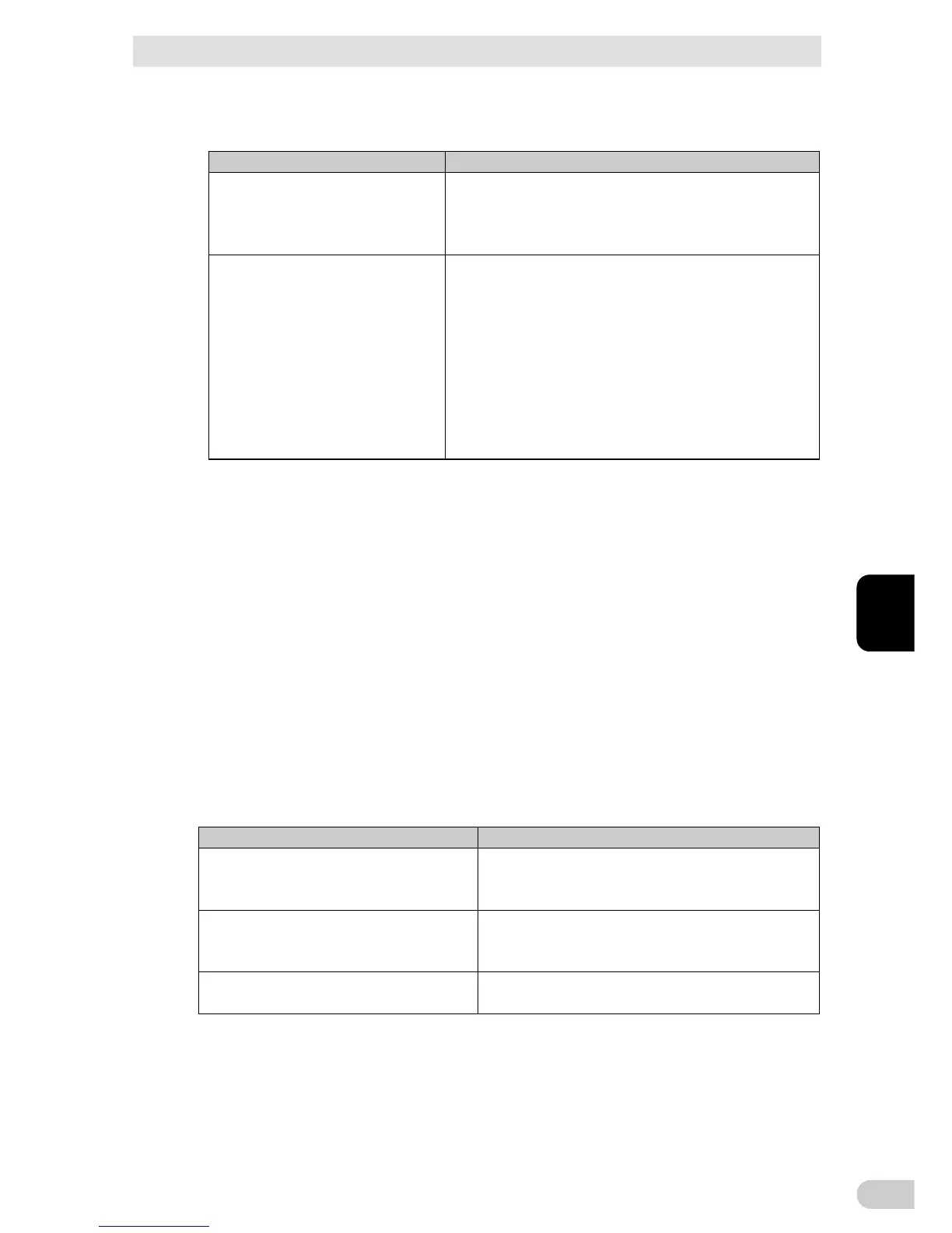
6-2-1 Contact signal connector (female D-SUB 9pin)
Pin assignment
Pin
number
For jumper setting “SC07”
* Factory settings
For jumper setting “SC05/06”
9876
5 4 3 21
Front view
Screw size:
inch screw #4-40 UNC
1
Battery LOW signal output (BL)
NC
2 Trouble signal output (TR) Backup signal output (BU)
3
Backup stop signal input (BS)
Backup reverse signal output (NBU)
4 NC COMMON(COM)
5 COMMON(COM)
Battery Low Signal output (BL)
6 Remote ON/OFF input (-)
Backup stop signal input (BS)
7 Remote ON/OFF input (+) Remote ON/OFF input (-)
8 Backup signal output (BU) Trouble Signal output (TR)
9
Battery Replacement Signal output (WB)
Remote ON/OFF input (+)
6-2-2 Type of Input/Output signals
Backup Signal output (BU)
UPS
Contact signal card SC07
Low battery level signal output (BL)
Trouble Signal output (TR)
Battery Replacement Signal output (WB)
Remote ON/OFF Signal(*)
Input of the UPS Stop Signal
(BS)
*: The remote ON/OFF connector can be used.
Type of Output signals
The UPS has 4 kinds of output signals. The output circuit consists of an open collector
circuit using a photo coupler (a kind of electronic switch).
Signals Descriptions
Backup Signal output (BU) Stays ON during backup operation at a power failure.
Low battery level signal output (BL) Goes ON when the battery becomes weak during backup
operation at a power failure.
Trouble Signal output (TR) Goes ON when an internal failure of the UPS occurs or
when the battery life counter expires.
Battery Replacement Signal output
(WB)
Goes ON when the test determines that battery replace-
ment is necessary due to deterioration or when the bat-
tery life counter goes off-scale.
6 Using the contact signal functions
6-2 SC07 Contact signal card specifications
BN50T/BN75T/BN100T/BN150T/BN220T/BN300T
6
6-3
Type of Input signal
The UPS has 2 kinds of input signals.
Signals Descriptions
Input of the UPS Stop Signal (BS) When the BS signal is ON (High), the output of the UPS
is stopped after the time period specified in advance
has elapsed. The following settings are available on the
LCD (Note1).
Remote ON/OFF Signal Remote ON/OFF signals can be used to start and stop
the UPS, by using either an externally connected
contact or the ON/OFF status of the open collector
circuit.
When signal is OFF, the UPS will be turned on. When
signal is ON, the UPS will be turned off.
In the factory settings, the UPS stops operation when
this is short-circuited. (Note 2)
In addition, it is necessary to turn on the power supply
switch of UPS to use this function. (Note 3)
Note 1: The following functions related to BS signal can be setup at LCD.
1) BS Valid Range:
“Setting” - “Dry Contact” - “BSsignal ValidRange”
Always enabled: The BS signal is received either in Commercial Power Mode or
Battery Mode.
Enabled during Battery Mode: The BS signal is received only in Battery Mode.
2) BS Delay Time:
“Setting” - “Dry Contact” - “BSsignal Delay Time”
You can set the amount of time between when the BS signal is received and when
the output of the UPS is stopped.
Note 2: If you want the UPS to stop operation when this is open, or if you want to disable this
function, specify OFF or disable in “Setting” – “Dry Contact” – “Remote ON/OFF Logic”.
Note 3: When there is no AC power supply, it is not possible to start up UPS by the remote
ON/OFF signals even though cold start is set ON.
6-2-3 Contact Signal ratings
Signals Ratings
Signal output (BL, TR, BU, WB, NBU) Photo coupler ratings
-Applicable voltage: 35 VDC or less
-Maximum current: 20 mA
UPS Stop Signal input (BS) Input voltage
-HIGH(ON) 5 to 12 VDC
-LOW(OFF) 0.7 VDC or less
Remote ON/OFF Signal Voltage between terminals: 10 VDC
Current when closed: max.10 mA