Product Specifications
Motion Control Unit
3
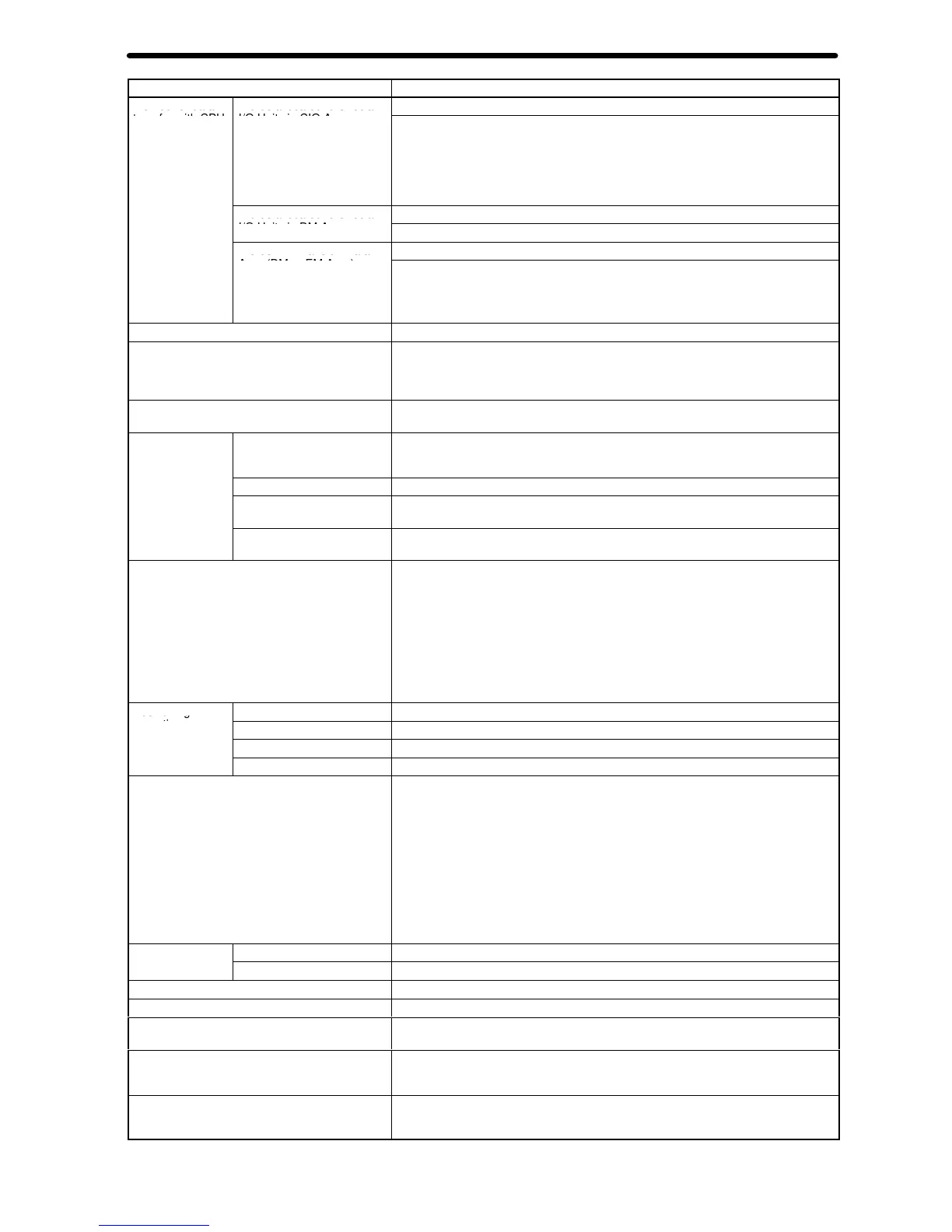
Model
number
C200H-MC221
Method for data
W
ords allocated to Special
20 words/Unit (uses 2 unit numbers.)
I/O Units in CIO Area
CPU Unit to MC Unit:
Program numbers, cycle start (MC program operation command), origin search
command, automatic/manual mode switching, etc.
MC Unit to CPU Unit:
Status: Positioning completed, zones, busy flag, etc.
Monitor data: Present position, error codes, M codes, etc.
W
ords allocated to Special
2 words used out of 100 words allocated
I/O Units in DM Area
Expansion Data words are specified in initial settings.
W
ords in Expansion Data
Area (DM or EM Area)
CPU Unit to MC Unit:
Data transfer area specifications, present position preset values, etc.
MC Unit to CPU Unit:
System error codes, task error codes, ef
fective program numbers, etc.
Controlled servodrivers Analog input servodrivers (Example: OMRON OMNUC H, M, or U Series)
Encoder interface
Line receiver input; maximum response frequency: 250 kp/s (before multiplication)
Pulse ratio: 4 (fixed)
Note: The applicable absolute encoder is the OMRON OMNUC U Series.
Built-in program language
G language (Started by receiving a start command from the CPU Unit ladder
diagram program.)
Control
Control method
Speed reference voltage output-type semi-closed loop system, using incremental
and absolute encoder inputs (automatic trapezoidal or S-curve
acceleration/deceleration method)
Number of controlled axes
2 axes max.
Number of simultaneously
controlled axes
2 axes max.
PTP (independent) control Multitasking can be used to execute independent operating modes and programs for
each axis.
Automatic/Manual Mode (for each task)
Automatic Mode: Mode for executing MC program created in G language.
Manual Mode: Mode for executing manual commands from CPU Unit (PC interface
area) or T
eaching Box.
Note: The Automatic and Manual Modes are switched according to the PC interface
area of the CPU Unit.
There are a total of 10 Manual Mode commands, including origin search, reference
origin return, jogging, and present position preset.
The operation command (cycle start) is started in Automatic Mode using the PC
interface area of the CPU Unit.
Positioning
Independent
Independent operations for a maximum of two axes
operations
Linear interpolation
Linear interpolation for a maximum of two axes
Circular interpolation
Circular interpolation for a maximum of two axes on a plane.
Interrupt feeding
Operations for each axis
Position specification method Operating positions can be specified in MC programs by using one of the following
three methods.
Direct Specification of Coordinate V
alues
Example: When G00 X100 is specified with absolute specification, the X axis moves
to a position of 100.
Address Specification of Position Data
Example: When G00 XA0000 is specified, the axis moves to the position set as
position data address 0000.
Indirect Register Specification
Example: When G00 X(E00) is specified, the X axis moves to the position set as the
position data address in the E00 indirect register
.
Control unit
Minimum setting unit
1, 0.1, 0.01, 0.001, 0.0001
Units
mm, inch, degree, pulse (There is no unit conversion function.)
Maximum command value
–39,999,999 to +39,999,999
Acceleration/deceleration curve
T
rapezoidal or S-curve (Can be selected for each axis.)
Acceleration/deceleration time
Individual acceleration/deceleration settings possible: 0 to 9,998 ms (2-ms
increments)
Speed reference
Speed control for a maximum of two axes.
When the unit is pulses, the setting range is from 1 p/s to 1,000 kp/s (after
multiplication by 4).
Feed rate (PTP operation) specification method
Can be set for each axis.
Feed rate = High speed
×
Override value/100
Real-time speed can be changed by altering the override value.
 Loading...


