256
Index Registers Section 6-2
Stack Processing
Stack instructions act on specially defined data tables called stacks. Data can
be drawn from a stack on a first-in first-out (FIFO) or last-in first-out (LIFO)
basis.
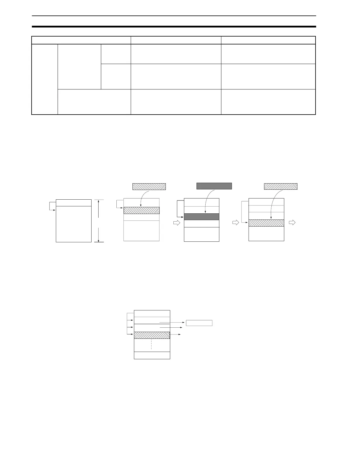
A particular region of I/O memory must be defined as a stack. The first words
of the stack indicate the length of the stack and contain the stack pointer. The
stack pointer is incremented each time that data is written to the stack to indi-
cate the next address where data should be stored.
Note Actually, the first two words of the stack contain the PLC memory address of
the last word in the stack and the next word contains the stack pointer.
FIFO (First-in First-out) Processing
The following diagram shows the operation of a first-in first-out (FIFO) stack.
Table
process-
ing
Tables with one-
word records
(Range instruc-
tions)
Basic pro-
cessing
Find values such as the checksum, a
particular value, the maximum value,
or minimum value in the range.
FCS(180), SRCH(181), MAX(182),
MIN(183), and SUM(184)
Special
processing
Perform various other table process-
ing such as comparisons or sorting.
Combine Index Registers with instruc-
tions such as SRCH(181), MAX(182),
MIN(183), and comparison instruc-
tions.
Tables with multiple-word
records
(Record-table instructions)
Process data in records that are sev-
eral words long.
Combine Index Registers with instruc-
tions such as DIM(631), SETR(635),
GETR(636), and comparison instruc-
tions.
Processing Purpose Instructions
B
A
B
Pointer address
Pointer address
Pointer address
Stack
region
A
Pointer address
A
C
A
C
B
(The above diagram shows
the status of the pointer
data before data is added.)
A
A
B
Pointer address
Reads the oldest word of data stored
in the stack. Each time that a word is
read, the pointer is decremented by one
to indicate the next address for storage.
X
C
 Loading...


