43
Basic Concepts Section 2-1
Basic Ladder Program Concepts
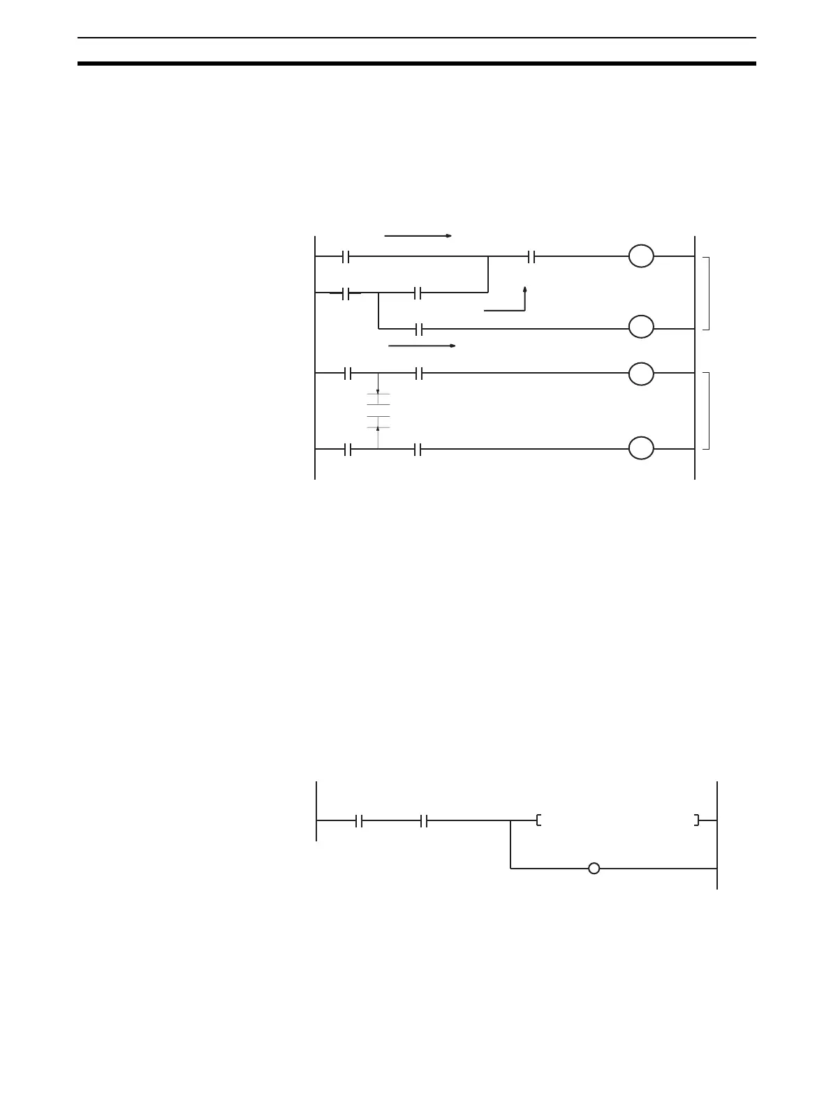
1,2,3... 1. The power flow in a program is from left to right. Power flows in rungs “a”
and “b” as though diodes were inserted. Rungs must be changed to pro-
duce operation that would be the same as ordinary circuits without a di-
odes. Instructions in a ladder diagram are executed in order from the left
bus bar to the right bus bar and from top to bottom. This is the same order
as the instructions are listed in mnemonic form.
Order of execution Mnemonic
(1)LD A (9) AND E
(2)LD C (10)OUT R2
(3)OUT TR0 (11)LD A
(4)AND D (12)AND B
(5)OR LD (13)OUT R1
(6)AND B (14)LD C
(7)OUT R1 (15)AND D
(8)LD TR0 (16)OUT R2
2. There is no limit to the number of I/O bits, work bits, timers, and other input
bits that can be used. Rungs, however, should be kept as clear and simple
as possible even if it means using more input bits to make them easier to
understand and maintain.
3. There is no limit to the number of input bits that can be connected in series
or in parallel in series or parallel rungs.
4. Two or more output bits can be connected in parallel.
Signal flow
A
C
A
C
D
E
B
D
B
R1
R2
R1
R2
(1)
(2) (3) (4)
(5)
(6) (7)
(8) (9)
(10)
(13)
(16)
(11) (12)
(14)
(15)
a
b
TIM 0000 #0100
0002
00
0000
00
0000
05
 Loading...


