20
I/O Specifications Section 3-1
3-1 I/O Specifications
3-1-1 Input Specifications
General-purpose Input Specifications
Note 1. The power supply voltage on the line driver side is 5 V ±5%.
2. The input time constant can be set to 0, 0.5, 1, 2, 4, 8, 16, or 32
µs.
When it is set to 0 ms, the delay due to internal components results in an
ON delay of 30
µs max. for IN0 to IN5 (2 µs max. for IN6 to IN9) and an
OFF delay of 150
µs max. for IN0 to IN5 (2 µs max. for IN6 to IN9).
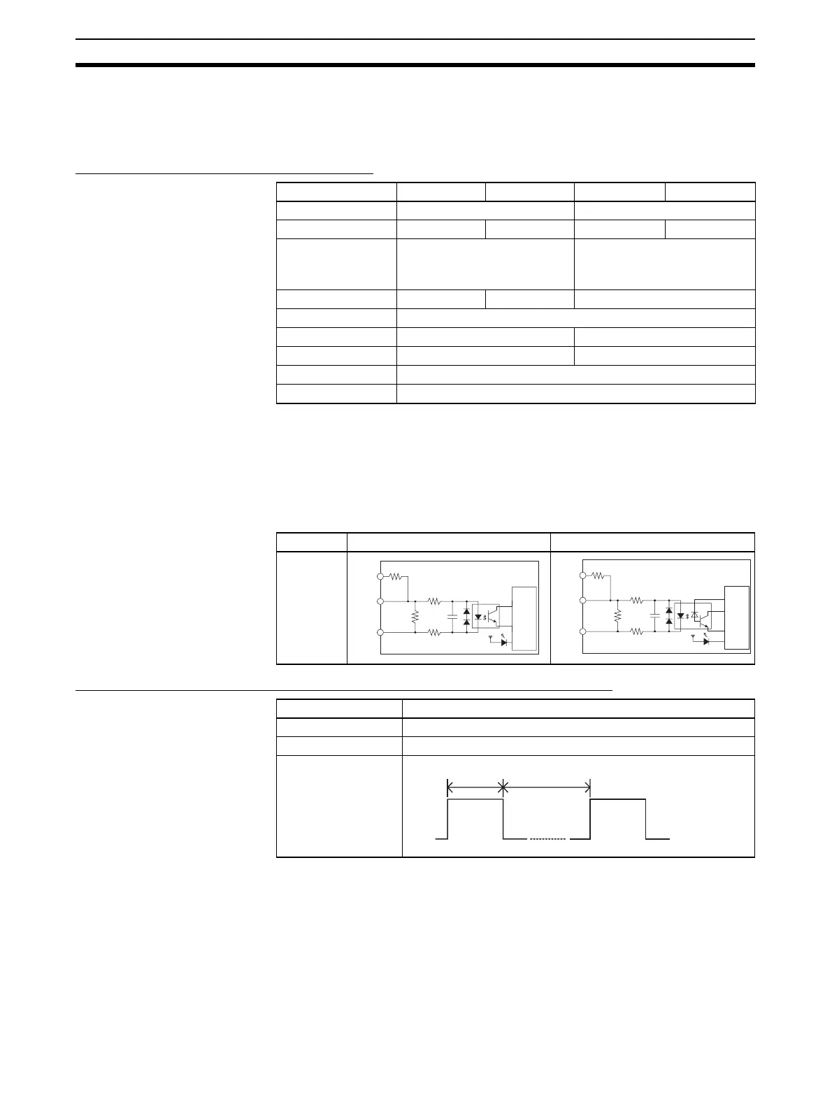
Circuit Configuration
Interrupt Input and Quick-response Input Specifications (IN0 to IN3)
Inputs IN0 to IN5 IN6 to IN9 IN0 to IN5 IN6 to IN9
Input type Two-wire Sensor Line driver inputs
Input current 6.0 mA typical 5.5 mA typical 13 mA typical 10 mA typical
Input voltage 24 V DC +10%, −15% RS-422A line driver
AM26LS31 standards
(See note 1.)
Input impedance 3.6 kΩ 4.0 kΩ ---
Number of circuits 1 common, 1 circuit
ON voltage/current 17.4 V DC min., 3 mA min. ---
OFF voltage/current 5 V DC max., 1 mA max. ---
ON delay 8 ms max. (See note 2.)
OFF delay 8 ms max. (See note 2.)
Input IN0 to IN5 IN6 to IN9
Circuit
configura-
tion
Item Specifications
ON delay 30 µs max.
OFF delay 150 µs max.
Response pulse
24 V
LD+
0 V/LD−
3.6 kΩ
100 Ω
750 Ω
100 Ω
1,000 pF
Internal circuits
24 V
LD+
0 V/LD−
4.0 kΩ
1.5 kΩ
100 Ω
100 Ω
1,000 pF
Internal circuits
ON
OFF
30 µs min 150 µs min