34
Wiring Examples Section 3-3
input. To prevent a false input, it is possible to prepare an application pro-
gram incorporating a timer delaying inputs from the sensor for a set time
after the sensor's power supply is turned ON until the sensor's operation
has stabilized.
Example Programming The sensor's power supply status is read with CIO 000000. The timer pro-
vides a delay until the sensor's operation has stabilized (100 ms for an
OMRON Proximity Sensor.)
Once TIM 0000 goes ON, output CIO 000100 will be turned ON when a sen-
sor input is received in input bit CIO 000001.
Output Wiring Precautions
Output Short Protection The output or internal circuitry might be damaged when the load connected to
an output is short-circuited, so we recommend installing a protective fuse in
each output circuit. Use a fuse with a capacity about two times greater than
the rated output capacity.
TTL Connections A TTL device cannot be connected directly because of the transistor's resid-
ual voltage. In this case, connect to a TTL Unit after receiving signals with a
CMOS IC. Also, a pull-up resistor must be used with the transistor output.
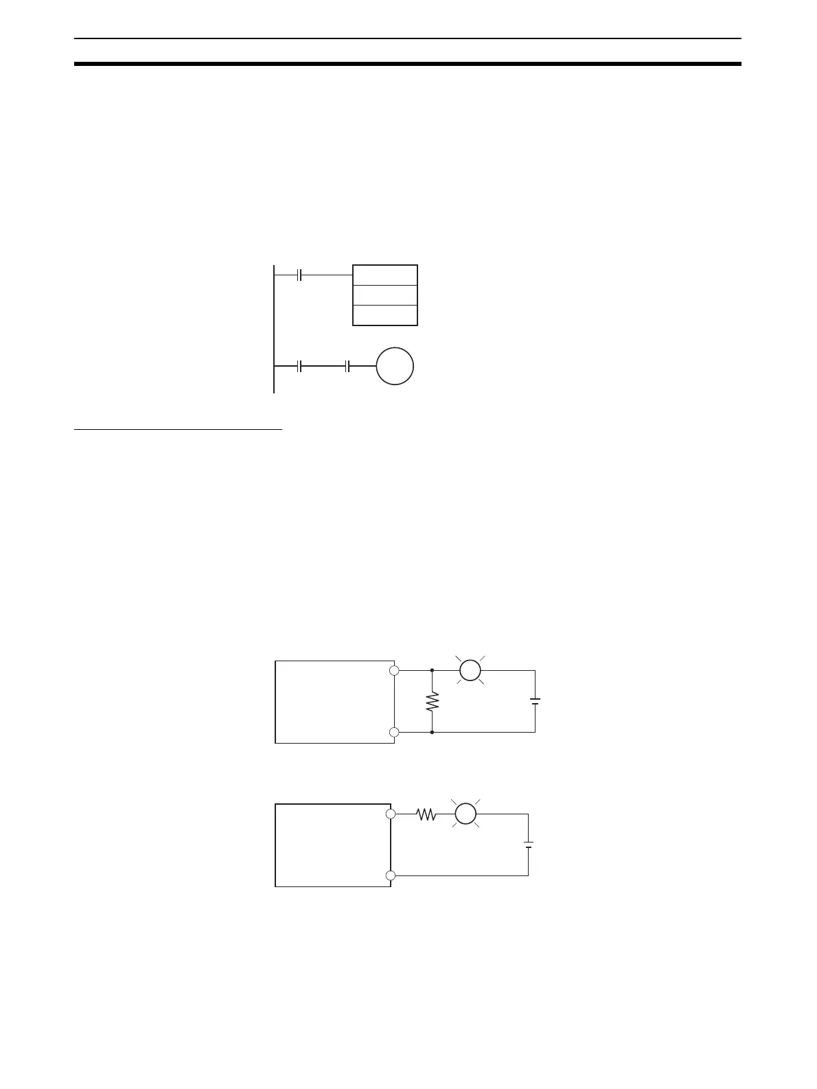
Inrush Current
Considerations
When switching a load with a high inrush current, such as an incandescent
light bulb, there is a risk of damaging the output transistor. Suppress the
inrush current using one of the methods shown below.
TIM
0000
#0001
000000
T0000 000001
000100
OUT
R
COM
L
+
OUT
R
COM
L
+
Method 1
Method 2
CJ1M CPU Unit's
built-in I/O
CJ1M CPU Unit's
built-in I/O
This method draws a dark current that is approximately
one-third of the rated value of the light bulb.
This method uses a limiting resistor.