42
Wiring Examples Section 3-3
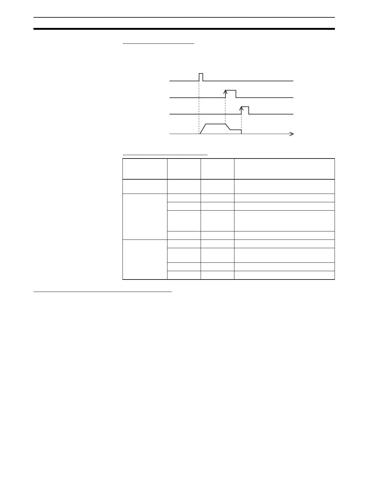
Origin Search Operation
The origin search operation is completed when the rising edge of the Origin
Proximity Input Signal is detected and then the rising edge of the Origin Input
Signal is detected.
Example PLC Setup Settings
Operating Mode 1 Connection Example
In operating mode 1, the Error Counter Reset Output is turned ON when the
origin location is determined by detection of the rising edge of the Origin Input
Signal.
In this example, a servo driver is used and the encoder's phase-Z output is
used as the Origin Input Signal terminal. The servo driver is an OMRON W-
series Servo Driver.
Programming
Console
address
Bits Setting Function
256 00 to 03 1 hex Enable origin search function for pulse
output 0.
257 00 to 03 0 hex Operating Mode 0
04 to 07 0 hex Reverse mode 1
08 to 11 1 hex Read Origin Input Signal after Origin
Proximity Input Signal goes from OFF
to ON.
12 to 15 0 hex Search direction is CW.
268 00 to 03 0 hex Limit Input Signal is a NC contact.
04 to 07 1 hex Origin Proximity Input Signal is a NO
contact.
08 to 11 1 hex Origin Input Signal is a NO contact.
12 to 15 0 hex ---
ORG(889)
instruction execution
Origin Proximity
Input Signal
Origin Input
Signal
Pulse signal
Time