39
Wiring Examples Section 3-3
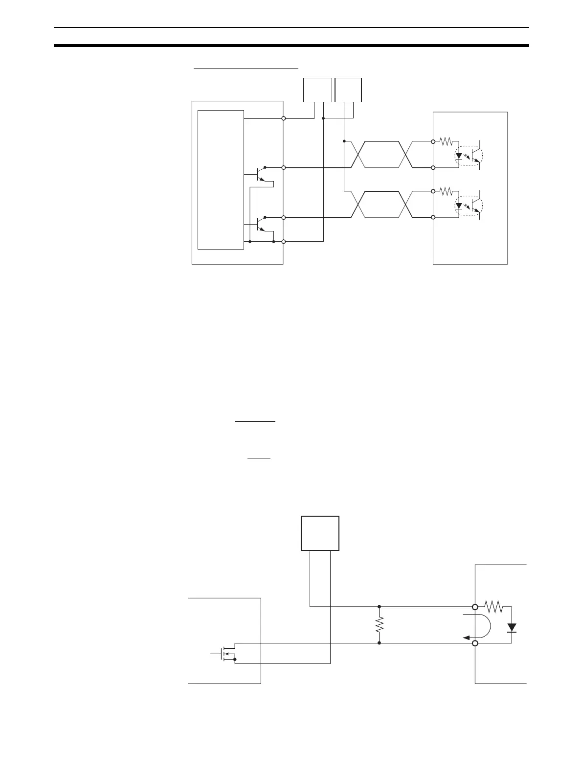
Connection Example 2
Note The terms in parentheses are for pulse + direction outputs.
!Caution When the output is being used as a pulse output, connect a load that requires
an output current between 7 and 30 mA. The Unit's internal components may
be damaged if the current exceeds 30 mA.
If the current is below 7 mA, the output waveform's rising edge and falling
edge will be delayed and the output frequency ratings may not be met. If the
load requires less than 7 mA, install a bypass resistor so that the circuit draws
a current greater than 7 mA (10 mA is recommended.)
Use the following equations to determine the bypass resistor requirements.
Circuit Example
31/33
(31/32)
37
32/34
(33/34)
39, 40
++
−−
(+)
(+)
(−)
(−)
CJ1M CPU Unit
24-V DC
power
supply for
outputs
CW pulse
output
(Pulse
output)
CCW pulse
output
(Direction
output)
24-V DC
power
supply
Motor driver
(5-V input type)
5-V DC
power
supply
R ≤
V
CC
I
OUT
− I
IN
Power W ≥
R
V
CC
2
× 4 (Tolerance)
V
CC
: Output voltage (V)
I
OUT
: Output current (A)
(7 to 30 mA)
I
W
: Driver input current
R: Bypass resistance (Ω)
V
CC
+
−
I
OUT
←
↓
R
I
IN
↓
CJ1M CPU Unit
Power
supply
Driver
Bypass resistor