6
Serial Communications Settings
6. Serial Communications Settings
This section describes the contents of parameter settings and wiring that are all defined in this
document.
6.1. Parameters
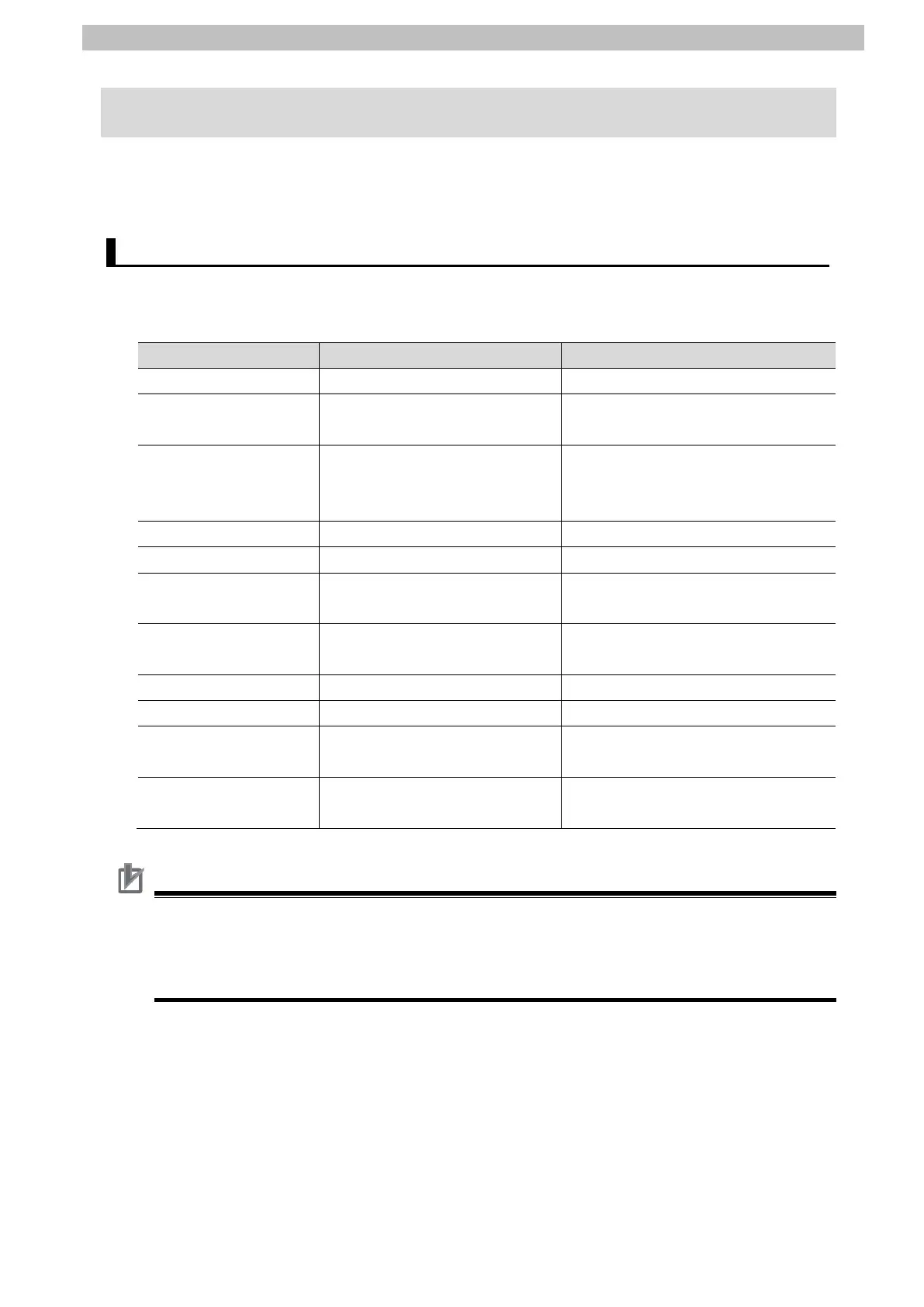
The parameters required for connecting PLC and Driver using the serial communications are
shown below.
Item PLC (Serial Communications Unit) Driver
Unit number 0 -
Address number
(Slave address)
- 1
(SW1: 1)(SW5-No.1: OFF)
Communications
(Connection) port
Port 1 (RS-422/485) RS-485 communication connector (CN7)
or RS-485 communication connector
(CN8)
Termination resistor Yes (TERM: ON) Yes (SW3-No.4: ON)
2-wire or 4-wire 2-wire (WIRE: 2) 2-wire (Fixed)
Serial communications
mode
Serial Gateway -
Data length
(Transmission character)
8 bits 8 bits (Fixed)
Stop bits 1 bit 1 bit (Default)
Parity (Parity bit) Even (Default) Even (Default)
Transmission rate
(Baud rate)
115,200 bps
115,200 bps(SW4: 4)
Communications protocol
selection
- Modbus RTU protocol
(SW5-No.2: ON)
Precautions for Correct Use
This document describes the setting procedures of CJ1W-SCU42 Serial Communications
Unit with the unit number 0 and communications (connection) port 1.
To connect devices under different conditions, change the CIO area and the control word of
CMND instruction used in the program. Refer to Section 9. Program for details.

 Loading...


