EasyManuals Logo

Omron CJ2M-CPU Series Connection Guide

Omron CJ2M-CPU Series
64 pages
To Next Page IconTo Next Page
To Previous Page IconTo Previous Page
Page #20 background imageLoading...
Page #20 background image
7
Serial Communications Connection Procedure
17
7.3. PLC Setup
Set up PLC.
7.3.1. Hardware Settings
Set the hardware switches on Serial Communications Unit and connect the cables.
Precautions for Correct Use
Make sure that the power supply is OFF when you set up.
Make sure that PLC is powered
OFF.
*If it is ON, the settings
described in the following steps
and subsequent procedures
may not be applicable.
2
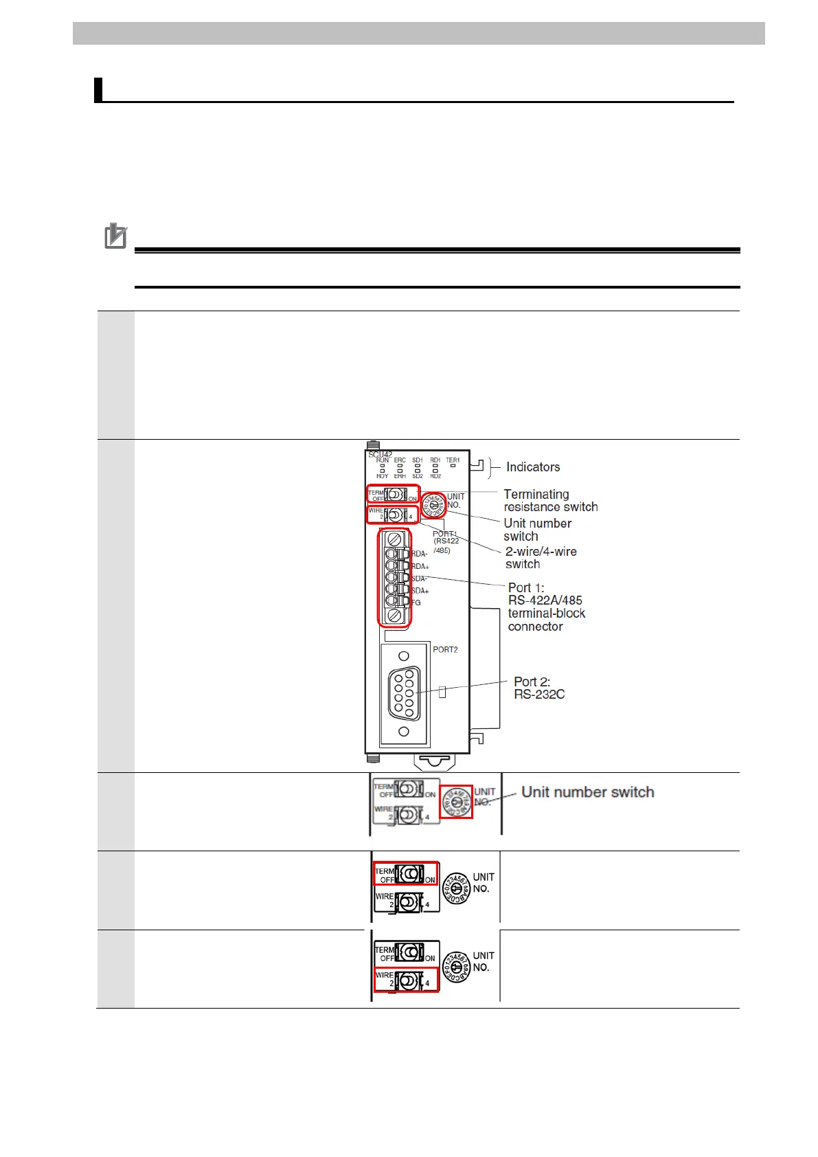
Check the positions of the
hardware switches and Port 1 by
referring to the figure on the
right.
Set Unit number switch to 0.
*The unit number is set to 0 as
the factory default setting.
Set Terminating resistance
ON/OFF switch to ON.
(Terminating resistance ON)
5
Set 2-wire or 4-wire switch to 2
(2-wire).
TERM (Terminating resistance ON/OFF switch)
OFF: Terminating resistance OFF
ON: Terminating resistance ON
WIRE (2-wire or 4-wire switch)
2:2-wire;4:4-wire

Other manuals for Omron CJ2M-CPU Series

Questions and Answers:

Question and Answer IconNeed help?

Do you have a question about the Omron CJ2M-CPU Series and is the answer not in the manual?

Omron CJ2M-CPU Series Specifications

General IconGeneral
Power Supply24 VDC
Number of InstructionsOver 400 instructions
ModelCJ2M-CPU11, CJ2M-CPU12, CJ2M-CPU13, CJ2M-CPU14, CJ2M-CPU15
Program Capacity5K steps to 60K steps
I/O CapacityUp to 2, 560 points
Communication PortsEthernet, USB, RS-232C
Execution Time0.04 µs per basic instruction
Operating Temperature0 to 55°C
Position ControlSupported
High-speed Counter100 kHz max.
Pulse Output100 kHz max.
Maximum Units40 units
Storage Temperature-20 to 75°C
Interrupt InputsSupported

Related product manuals