Home
Omron
Controller
CK3W-GC 00 Series
Omron CK3W-GC 00 Series User Manual
4
of 1
of 1 rating
218 pages
Give review
Manual
Specs
To Next Page
To Next Page
To Previous Page
To Previous Page
Loading...
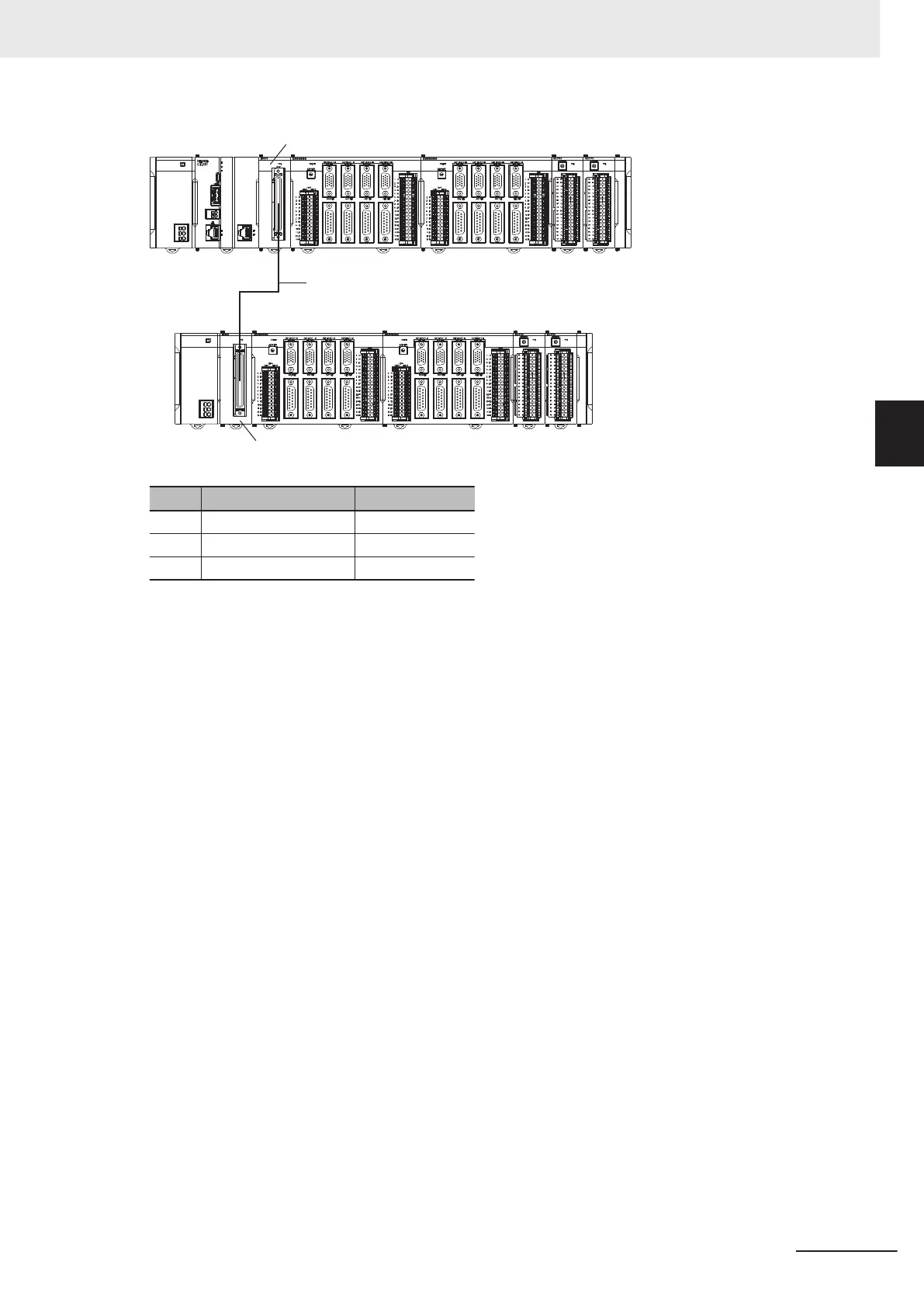
(A)
(C)
(B)
Letter
Name
Model
A
Expansion Master Unit
CK3W-EXM01
B
Expansion cable
CK3W
-CAX003A
C
Expansion Slave Unit
CK3W-EXS02
3 Configuration Units
3-61
CK3M-series Programmable Multi-Axis Controller User's Manual Hardware (O036)
3-6 Expansion Master Unit and Expansion Slave Unit
3
3-6-4 System Configuration
104
106
Table of Contents
Introduction
3
Intended Audience
3
Applicable Products
3
Manual Structure
4
Page Structure
4
Special Information
5
Sections in this Manual
7
Wiring 7
7
Table of Contents
8
Terms and Conditions Agreement
12
Warranty, Limitations of Liability
12
Application Considerations
13
Disclaimers
13
Safety Precautions
15
Definition of Precautionary Information
15
Symbols
15
Warning
16
Cautions
18
Precautions for Safe Use
19
Precautions for Correct Use
24
Regulations and Standards
26
Conformance to EU Directives
26
Condition for Compliance with EU Directives
27
Conformance to UL and CSA Standards
27
Conformance to KC Certification
27
Versions
28
Checking Versions
28
Related Manuals
29
Terminology
30
Revision History
31
Introduction to Motion Controllers
33
Features and System Configuration
34
Motion Controller Features
34
Introduction to the System Configurations
34
Support Software
36
CK3M-Series Operating Procedure
37
System Configuration
39
Basic Configuration
40
CK3W Unit Configuration
40
Ethercat Network Configuration
40
Ethercat Network Configuration
41
Connecting to the Power PMAC IDE
43
Ethernet Network Configuration
44
Configuration Units
45
Section 3 Configuration Units
47
CPU Unit
47
Models and Specifications
47
Part Names and Functions
49
Operation Status Indicators
50
Watchdog Output Terminal Block
51
USB Memory Device
52
Power Supply Unit
54
Models and Specifications
54
Part Names and Functions
55
Axis Interface Unit
56
Models and Specifications
56
Part Names and Functions
58
Operation Status Indicators
59
Address Switch Setting
60
Encoder Connector Specifications
60
Encoder Loss Detection
65
Pulse Input Timing Specifications for Digital Quadrature Encoder
66
Input Specifications for Sinusoidal Encoder
68
Outflag Function
70
Amplifier Connector Specifications
71
DA Output Method
74
Directpwm Output Method
75
Flag Connection Terminal Block Specifications
76
General Digital I/O Connection Terminal Block Specifications
80
Digital I/O Unit
87
Models and Specifications
87
Part Names and Functions
91
Operation Indicators
92
Address Switch Setting
92
Terminal Arrangement
93
I/O Data
94
Analog Input Unit
96
Models and Specifications
96
Part Names and Functions
97
Operation Indicators
98
Address Switch Setting
98
Terminal Arrangement
99
Analog Input Data
100
Input Filter
101
Expansion Master Unit and Expansion Slave Unit
103
Models and Specifications
103
Part Names and Functions
104
Operation Indicators
104
System Configuration
104
Installation
107
Section 4 Installation
108
Processing at Power on and Power off
108
Power on Operation
108
Power off Operation
108
Fail-Safe Circuits
110
Mounting Units
111
Installation in a Control Panel
111
Connecting Adjacent Units
115
Mounting to DIN Track
116
DIN Track and Accessories
118
Assembled Appearance and Dimensions
119
Control Panel Installation
123
Temperature
123
Humidity
124
Vibration and Shock
125
Atmosphere
125
Electrical Environment
125
Grounding
130
Power Supply Wiring
136
Power Supply Unit CK3W-PD048
136
Power Supply Used
136
Applicable Wires
136
Grounding
137
Required Tools
138
Connecting Ferrules
138
Connecting Twisted Wires/Solid Wires
138
Removing Wires
139
CPU Unit Wiring
141
Laying the Ethercat Network
141
Laying the Ethernet Network
146
Watchdog Timer Output Wiring
149
USB Memory Device Connection
151
Axis Interface Unit Wiring
152
Encoder Connector Wiring
152
Amplifier Connector Wiring
158
Flag Terminal Block/General I/O Terminal Block Wiring
160
Digital I/O Unit Wiring
167
Wiring the Terminals
167
Precautions When Connecting a Two-Wire DC Sensor
170
Precautions When Connecting to Digital Output
172
Analog Input Unit Wiring
174
Wiring the Terminals
174
Expansion Master Unit and Expansion Slave Unit Wiring
178
Troubleshooting
179
Types of Errors
180
Using the Indicators to Check Errors
181
Indicator Types
181
Procedure for Identifying Errors
181
Troubleshooting for Errors
183
Fatal Errors in the CPU Unit
183
Non-Fatal Errors in the CPU Unit
184
Initialization of CPU Unit Using USB Memory
186
Sys.status Register
187
Sys.status Register List
187
Details of Flags
187
Inspection and Maintenance
197
Section 7 Inspection and Maintenance
198
Cleaning and Maintenance
198
Cleaning
198
Periodic Inspections
198
Maintenance Procedures
200
Unit Replacement Precautions
200
Backup
200
Unit Replacement
200
Appendices
203
A-1 General Specifications
204
A-2 Dimensions
205
A-2-1 CPU Unit
205
CPU Unit
205
A-2-2 Power Supply Unit
206
A-2-3 Axis Interface Unit
206
A-2-4 CK3W-MD and CK3W-AD Units
207
A-2-5 Expansion Master Unit and Expansion Slave Unit
208
A-2-6 End Cover
209
Restrictions on Using the NX-Series Ethercat Coupler Unit
210
OMRON Servo Drive Connection Example
211
A-5 Version Information
212
A-6 How to Read the Lot Number
213
Index
215
Other manuals for Omron CK3W-GC 00 Series
Hardware User Manual
288 pages
4
Based on 1 rating
Ask a question
Give review
Questions and Answers:
Need help?
Do you have a question about the Omron CK3W-GC 00 Series and is the answer not in the manual?
Ask a question
Omron CK3W-GC 00 Series Specifications
General
Brand
Omron
Model
CK3W-GC 00 Series
Category
Controller
Language
English
Related product manuals
Omron CK3W-AX1515N
288 pages
Omron CK3M Series
218 pages
Omron CK3E Series
114 pages
Omron CK5M Series
114 pages
Omron CK5M-CPU 1 Series
114 pages
Omron CK5M-CPU1 1 Series
114 pages
Omron CK M-CPU1 1 Series
114 pages
Omron CQM1
312 pages
Omron CPM1
144 pages
Omron CQM1H
54 pages
Omron CJ2-CPU
430 pages
Omron CJ1W-DRM21
350 pages

 Loading...


