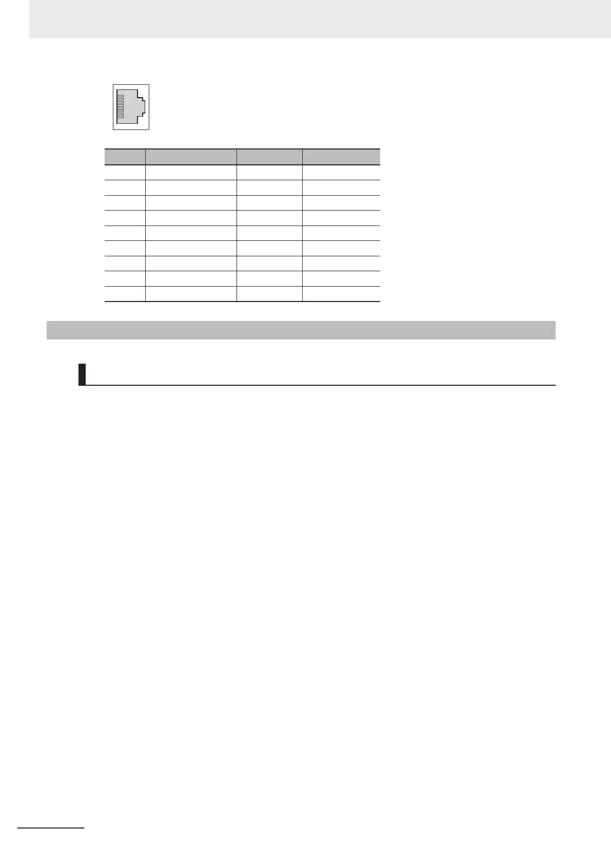
Pin No. Signal name Abbreviation Signal direction
1 Transmission data + TD+ Output
2 Transmission data − TD− Output
3 Reception data + RD+ Input
4 Not used. --- ---
5 Not used. --- ---
6 Reception data − RD− Input
7 Not used. --- ---
8 Not used. --- ---
Hood Frame ground FG ---
5-2-2
Laying the Ethernet Network
Installation Precautions
Basic precautions for the installation of Ethernet networks are provided below.
Precautions when Installing a Network
• When you install an Ethernet network, take sufficient safety precautions and follow the standards
and specifications. (Refer to "JIS X 5252" or to electrical facility technical references.)
An expert who is well trained in safety measures, standards, and specifications should be asked
to perform the installation.
•
Do not install Ethernet network equipment near sources of noise.
If the network must be installed in an area subject to noise, take steps to address the noise, such
as placing equipment in metal cases.
Precautions when Installing Communications Cables
• Check the following items on the communications cables that are used in the network.
a) Are there any breaks?
b) Are there any shorts?
c) Are there any connector problems?
• When you connect the cable to the communications connectors on devices, firmly insert the
communications cable connector until it locks in place.
• Do not lay the communications cables together with high-voltage lines.
• Do not lay the communications cable near devices that generate noise.
• Do not lay the communications cables in locations subject to high temperatures or high humidity.
• Do not lay the communications cables in locations subject to excessive dirt and dust or to oil mist
or other contaminants.
• There are limitations on the bending radius of communications cables. Check the specifications
of the communications cable for the bending radius.
5 Wiring
5-12
CK3M-series Programmable Multi-Axis Controller User's Manual Hardware (O036)

 Loading...


