3-6-2
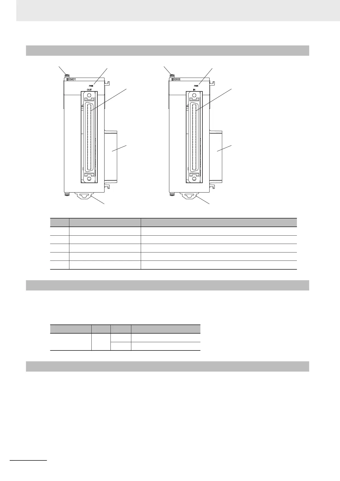
Part Names and Functions
(A)
(B)
(A)
(B)
(C)
(D)
(C)
(D)
(E) (E)
Letter Name Function
A Slider Holds the Units together.
B Power supply status indicator Shows the power supply status.
C Connector Connect the Expansion Master Unit and the Expansion Slave Unit.
D Unit connector Connector that connects to the Unit.
E DIN Track mounting hook Used to mount the Unit to a DIN Track.
3-6-3
Operation Indicators
Each LED indicator shows the unit operating status of the Expansion Master Unit or Expansion Slave
Unit.
The operating statuses corresponding to the colors and statuses of the indicators are shown below
.
Indicator name Color Status Description
PWR Green ON Power is supplied.
OFF Power is not being supplied.
3-6-4
System Configuration
You can use the Expansion Master Unit and the Expansion Slave Unit to connect an Expansion Rack
to the CPU Unit.
One Expansion Rack can be connected per CPU Unit.
Up to four CK3W Units (or up to two CK3W
-AX Units) can be installed to the Expansion Rack.
Connect the Expansion Master Unit adjacent to the right side of the CPU Unit. Connect the Expansion
Slave Unit adjacent to the right side of the Power Supply Unit.
3 Configuration Units
3-60
CK3M-series Programmable Multi-Axis Controller User's Manual Hardware (O036)

 Loading...


