Type Pin No. Cable color
Signal
U, V, W Serial Encoder
Pair 1 12 Blue Encoder Power Supply (+5 VDC)
14 White Encoder Power Supply (GND)
Pair 2 4 Black Hall sensor U Serial Encoder CLK+
9 Green Hall sensor V Serial Encoder CLK-
Pair 3 5 Yellow Hall sensor W Serial Encoder DAT+
10 Brown Hall sensor T Serial Encoder DAT-
Note The cable shield is connected to the connector shell of the encoder connector.
5-3-2
Amplifier Connector Wiring
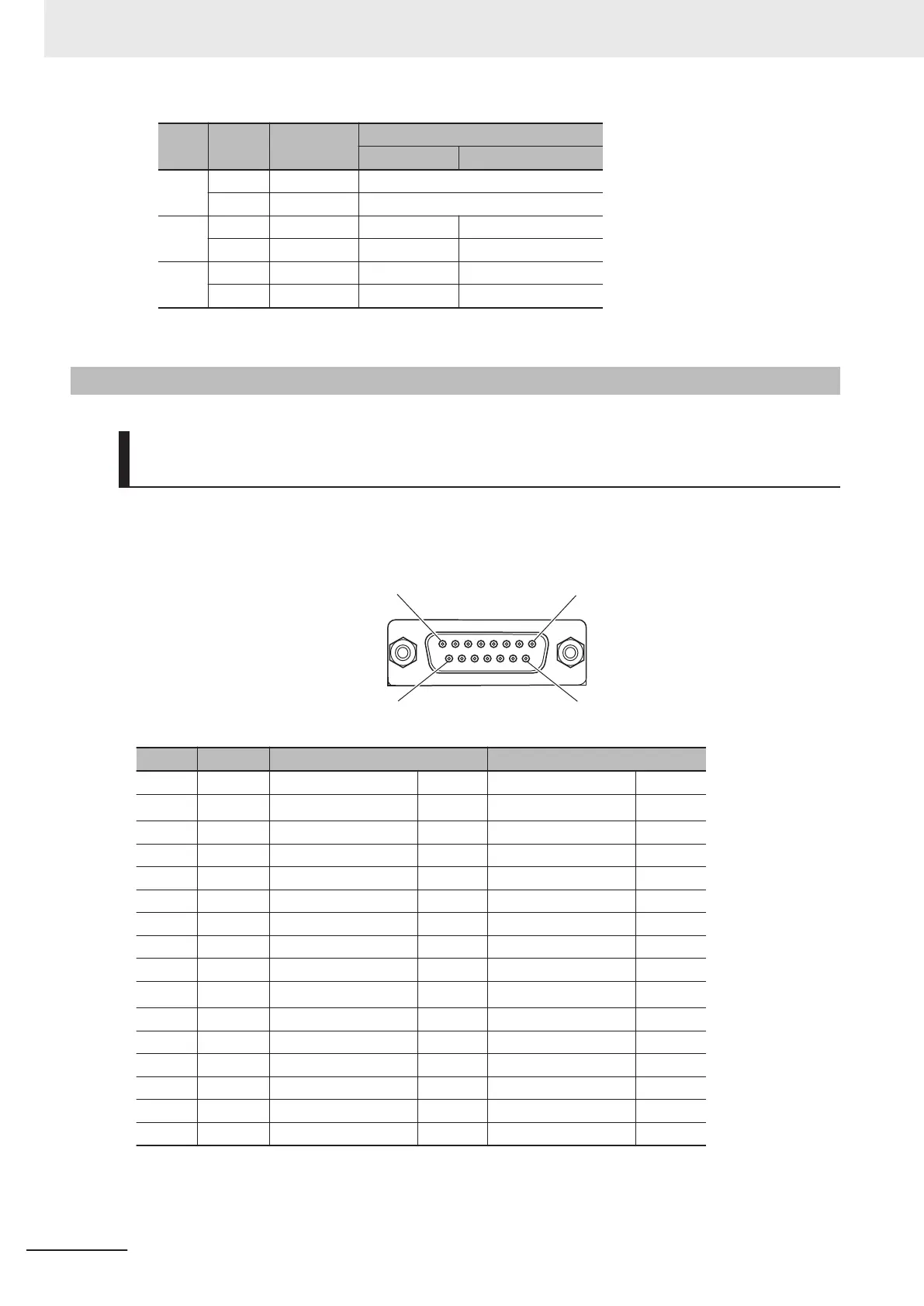
Connector Arrangement of FilteredPWM/TrueDAC Type Amplifier
Connector
This section describes the connector arrangement for the CK3W-AX1414£/-AX1515£ Units.
The Unit side connector is a D-sub 15-pin female connector (MIL-C-24308 compliant, lock screw
#4-40 UNC).
Pin No. Symbol During analog output During pulse output
1 DACA+ Analog output A+ Output Not wired -
2 DACB+
Analog output B+
*1
Output Not wired -
3 AGND Analog GND Common Not wired -
4 FAULT+ Fault input + Input Fault input + Input
5 PULSE+ Not wired - Pulse output + Output
6 DIR+ Not wired - Directional output + Output
7 AE_NO Amp enable NO Output Amp enable NO Output
8 AE_NC Amp enable NC Output Amp enable NC Output
9 DACA- Analog output A- Output Not wired -
10 DACB-
Analog output B-
*1
Output Not wired -
11 FAULT- Fault input - Input Fault input - Input
12 PULSE- Not wired - Pulse output - Output
13 DIR- Not wired - Directional output - Output
14 GND Not wired - GND Common
15 AE_COM Amp enable Common Common Amp enable Common Common
Shell SHELL Shield Shield
*1. In the FilteredPWM type, there is no analog output B.
5 Wiring
5-24
CK3M-series Programmable Multi-Axis Controller User's Manual Hardware (O036)

 Loading...


