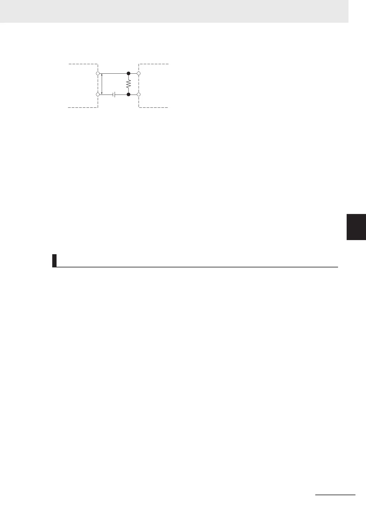
Two-wire sensor
General digital input
and flag input
V
R
V
C
C
R
V
CC
: Power supply voltage V
R
: Output residual voltage of sensor
V
ON
: ON voltage of general digital input and flag input I
OUT
: Sensor control output (load current)
V
OFF
: OFF voltage of general digital input and flag input I
leak
: Sensor leakage current
I
ON
: ON current of general digital input and flag input R: Bleeder resistor
I
OFF
: OFF current of general digital input and flag input
Precautions for Sensor Inrush Current
An incorrect input may occur due to sensor inrush current if a sensor is turned ON after the Unit
has started up to the point where inputs are possible.
Determine the time required for sensor operation to stabilize after the sensor is turned ON and take
appropriate measures, such as inserting an ON delay into the application program after turning ON
the sensor
.
Precautions When Connecting to General Digital Output
Output Short-circuit Protection
If a load connected to the output terminals is short-circuited, output components and printed circuit
boards may be damaged.
When you use a NPN type output that does not include the load short-circuit protection, incorporate
a protective fuse in the output. Use a fuse with a capacity of protection, around twice the rated out-
put.
Precautions for Inrush Current
When you use general digital output, steps must be taken to avoid damage to the output transistor
when connecting a load with a high inrush current such as an incandescent lamp.
Use either of the following methods to reduce the inrush current.
In countermeasure 1, the current consumption from the I/O power supply is increased although the
voltage supplied to the load L is not decreased.
In countermeasure 2, the voltage supplied to the load L is decreased although the current con-
sumption from the I/O power supply is not increased.
Select the appropriate countermeasures according to the operating conditions.
Countermeasure 1
Draw about 1/3 of the rated current consumed by the load.
5 Wiring
5-31
CK3M-series Programmable Multi-Axis Controller User's Manual Hardware (O036)
5-3 Axis Interface Unit Wiring
5
5-3-3 Flag Terminal Block/General I/O Terminal Block Wiring

 Loading...


