For the connector arrangement of the encoder connector, refer to 5-3-1
Encoder Connector Wiring on
page 5-18.
Isolation method Not isolated (between internal circuit and encoder circuit)
Encoder
power sup-
ply output
Rated output voltage 5 VDC
Output voltage range 4.9 to 5.25 VDC (5 VDC +5%/-2%)
Maximum output current 500 mA/channel or less
However
, the total output current of each Unit is 1 A or less.
Digital quad-
rature en-
coder input
*1
Input form Line receiver input (differential or single-ended input)
Counting unit Pulse
Input voltage Differential input: EIA standard RS-422A line driver levels
Single-ended input
*2
: ON voltage 3.0 V or more, OFF volt-
age 1.0 V or less
Maximum input voltage Differential input: EIA standard RS-422A line driver levels
Single-ended input: -0.3 to 6.0 VDC
Maximum response frequency Phases A, B, and C: 10 MHz
Encoder loss detection Differential input: Detectable
With single-ended input: Detection disabled
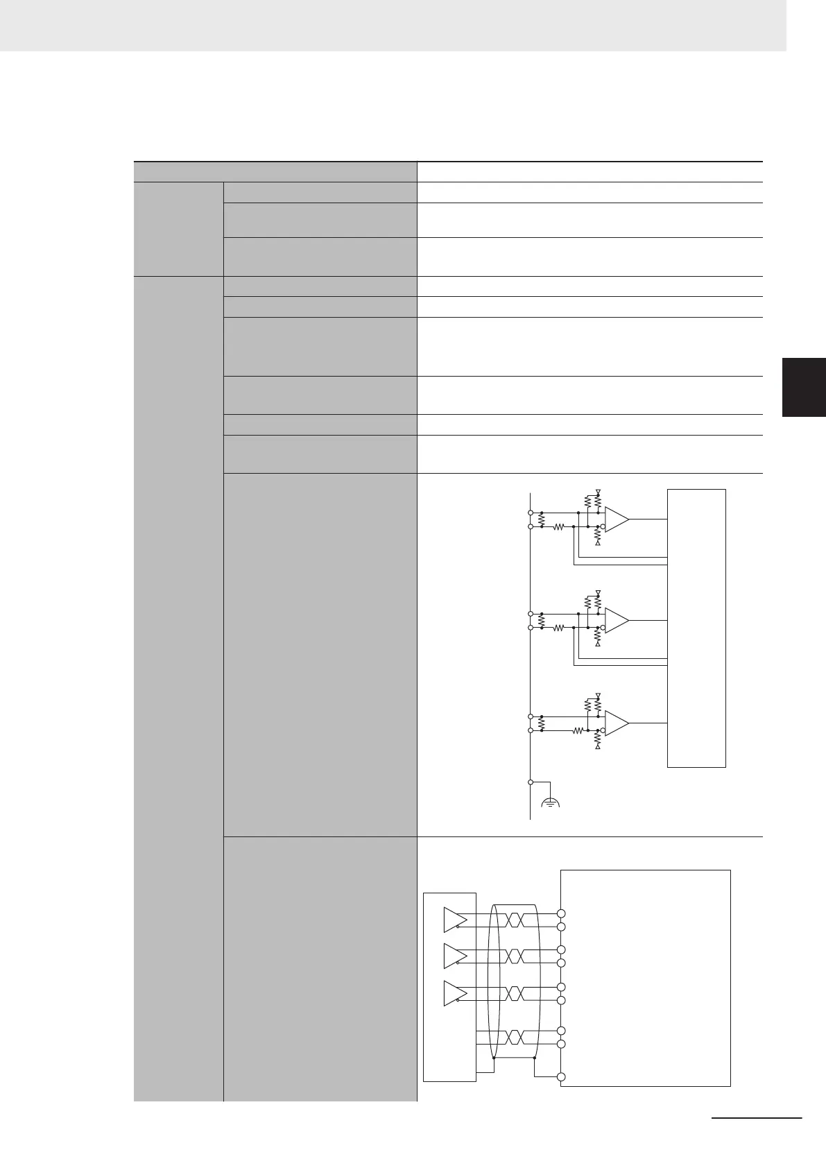
Circuit configuration
Encoder A+
Encoder A-
Internal
circuit
For encoder loss detection
For encoder loss detection
120
Ω
120
Ω
120
Ω
+5 V
+5 V
0 V
0 V
+5 V
0 V
Encoder B+
Encoder B-
Encoder C+
Encoder C-
Connector shell
FG
Terminal connection diagram With differential input
Encoder
Encoder A+
Encoder A-
Encoder B+
Encoder B-
Encoder C+
Encoder C-
Encoder power supply
(+5 VDC)
Encoder power supply
(GND)
Connector shell
+5 V
0V
+
-
+
-
+
-
3 Configuration Units
3-17
CK3M-series Programmable Multi-Axis Controller User's Manual Hardware (O036)
3-3 Axis Interface Unit
3
3-3-5 Encoder Connector Specifications

 Loading...


