3
Setting Connections 2 to 16
Set connections 2 to 16 in the same
way as described above.
For each connection, change the
Exclusive Owner number and other
data from 1 to up to 16.
For the T
arget V
ariable, set the value
in increments of +4, i.e., 768 is followed
by 772 for inputs and 769 is followed by
773 for outputs.
4
Select Device Bandwidth and make
sure that the bandwidth used by the de-
vice is within the specification range of
the PMAC.
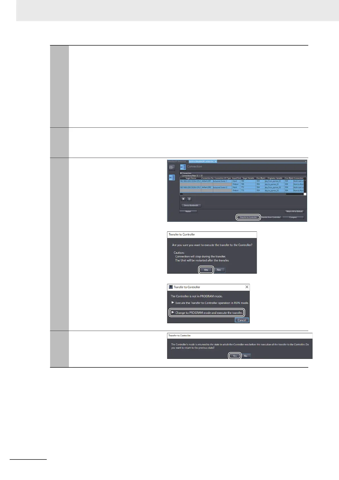
5
Click the T
ransfer to Controller button.
• If the message shown on the right
appears, click the Yes
button.
• If the message shown on the right
appears, select Change to
PROGRAM mode and execute the
transfer.
6
If the message shown on the right ap-
pears after completion of transfer, click
the
Yes button.
*1. These numbers specify the instance IDs of the Assembly objects. For more information, refer to CK3M/
CK5M-series Programmable Multi-Axis Controller User's Manual Hardware (Cat. No. O036), A-7-2
Assembly Object (Class ID: 04 Hex) or CK3E-series Programmable Multi-Axis Controller Hardware User’
s
Manual (Cat. No. I610), A-3-2 Assembly Object (Class ID: 04 Hex).
3 EtherNet/IP Connection Procedures
3-12
CK3E/CK3M/CK5M Series EtherNet/IP Connection Guide (O903)
 Loading...


