!
34
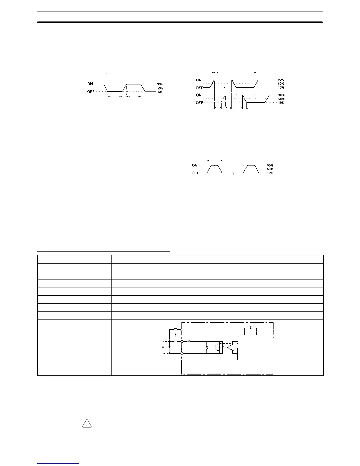
The minimum pulse widths for inputs IN00000 (A-phase input) and IN00001 (B-
phase input) are as follows:
100 µs min.
T
1
T
2
T
3
T
4
: 12.5 µs min.
Phase A
Phase B
50 µs min.
12.5 µs
min.
Pulse plus direction input mode, Up/down input
mode, Increment mode
Differential phase mode
12.5 µs
min.
T
1
T
2
T
3
T
4
The minimum pulse width for input IN00002 (Z-phase input) is as follows:
50 µs min.
500 µs
min.
Phase Z
Interrupt Inputs
Inputs IN00003 through IN00006 can be used as interrupt inputs (interrupt input
mode or counter mode) and quick-response inputs. The minimum pulse width
for these inputs is 50 µs.
Expansion I/O Unit Input Specifications
Item Specification
Input voltage 24 VDC
+10%
/
–15%
Input impedance 4.7 kΩ
Input current 5 mA typical
ON voltage 14.4 VDC min.
OFF voltage 5.0 VDC max.
ON delay 1 to 80 ms max. Default: 10 ms (See note.)
OFF delay 1 to 80 ms max. Default: 10 ms (See note.)
Circuit configuration
IN
IN
COM
4.7 kΩ
Internal
circuits
Input LED
750 Ω
Note The input time constant can be set to 1, 2, 3, 5, 10, 20, 40, or 80 ms in the PC
Setup.
Caution Do not apply voltage in excess of the rated voltage to the input terminal. It may
result in damage to the product or fire.
Specifications Section 2-1