33
2-1-3 I/O Specifications
CPU Unit Input Specifications
Item Inputs Specification
Input voltage All 24 VDC
+10%
/
–15%
Input impedance
IN00000 to IN00001 2.7 kΩ
IN00002 to IN00006 3.9 kΩ
IN00007 and up 4.7 kΩ
Input current
IN00000 to IN00001 8 mA typical
IN00002 to IN00006 6 mA typical
IN00007 and up 5 mA typical
ON voltage/current
IN00000 to IN00001 17 VDC min., 5 mA
IN00002 and up 14.4 VDC min., 3 mA
OFF voltage/current All 5.0 VDC max., 1 mA
ON delay All 1 to 80 ms max. Default: 10 ms (See note.)
OFF delay All 1 to 80 ms max. Default: 10 ms (See note.)
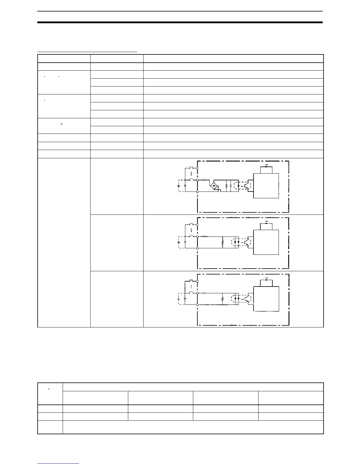
Circuit configuration
IN00000 to IN00001
680 Ω
0.01 µF
IN
IN
COM
2.7 kΩ
Internal
circuits
Input LED
IN00002 to IN00006
IN
IN
COM
3.9 kΩ
Internal
circuits
Input LED
750 Ω
IN00007 and up
IN
IN
COM
4.7 kΩ
Internal
circuits
Input LED
750 Ω
Note The input time constant can be set to 1, 2, 3, 5, 10, 20, 40, or 80 ms in the PC
Setup.
High-speed Counter Inputs
Inputs IN00000 through IN00002 can be used as high-speed counter inputs, as
shown in the following table. The maximum count frequency is 5 kHz in differen-
tial phase mode and 20 kHz in the other modes.
Input
Function
Differential phase mode Pulse plus direction
input mode
Up/down input mode Increment mode
IN00000 A-phase pulse input Pulse input Increment pulse input Increment pulse input
IN00001 B-phase pulse input Direction input Decrement pulse input Normal input
IN00002 Z-phase pulse input or hardware reset input
(IN00002 can be used as a normal input when it is not used as a high-speed counter input.)
Specifications Section 2-1