54
Floor Ducts
Leave at least 200 mm between the wiring and the top of the duct, as shown in
the following diagram.
200 mm min.
Metal plate (iron)
CPM2A I/O lines
Control cables and
CPM2A power lines
Power cables
Conduits
Separate the CPM2A I/O lines, power and control lines, and power cables, as
shown in the following diagram.
CPM2A I/O lines
Control cables and
CPM2A power lines
Power cables
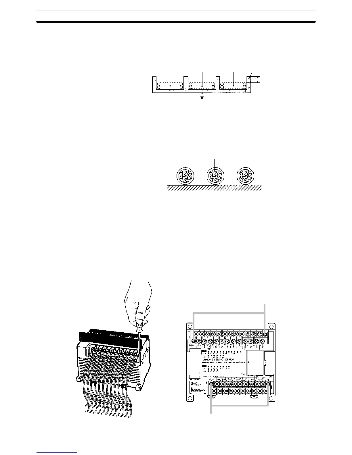
3-4-2 Removing the Terminal Block
The terminal block on the CPM2A CPU Unit can be removed. Use the following
procedure.
The terminal blocks on the Expansion Units and Expansion I/O Units cannot be
removed.
1, 2, 3... 1. Loosen the black screws at the ends of the terminal block as shown in the
following diagram.
Black screws
Black screws
Wiring and Connections
Section 3-4