58
3-4-5 Input Wiring
Wire the inputs to the CPM2A’s CPU Unit and Expansion I/O Units as shown in
the following diagrams. Use crimp terminals or solid wires (not stranded wire) to
connect to the PC. The power supply output terminals can be used with CPU
Units with AC power supplies.
Note When equipment must conform to the EC Directives (Low-voltage Directives),
use a power supply with double insulation or reinforced insulation.
Input Configuration The following diagrams show the input configurations.
Note Refer to Section 3 Memory Areas in the Programming Manual (W353) for details
on the allocation of input bits in CPM2A PCs.
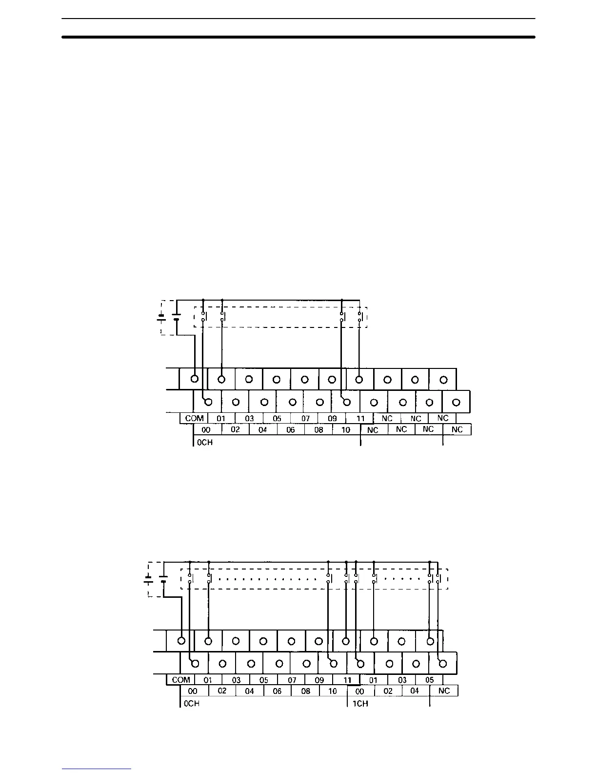
CPM2A-20CDR-j, CPM2A-20CDT-D, and CPM2A-20CDT1-D
Terminals 00 through 11 of “0CH” correspond to bits IR 00000 through IR 00011.
Input
devices
24 VDC
CPM2A-30CDR-j, CPM2A-30CDT-D, and CPM2A-30CDT1-D
Terminals 00 through 11 of “0CH” correspond to bits IR 00000 through IR 00011,
terminals 00 through 05 of “1CH” correspond to bits IR 00100 through IR 00105.
Input
devices
24 VDC
Wiring and Connections
Section 3-4