The OMRON CR_UGD4MINI Series is a Delta 3+1 Robot with an IP65 protection class, designed for high-speed pick-and-place applications. This user manual provides comprehensive information for safe and proper use, covering safety instructions, installation, model overview, robot settings, and specifications.
Function Description:
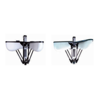
The CR_UGD4MINI Delta robot is a high-speed pick-and-place robot that utilizes state-of-the-art carbon composite materials and the latest servo drive technology. It is designed as a 3-axis (with an optional 4th rotational axis) Delta kinematic system, offering three degrees of freedom (X, Y, and Z) for the Tool Center Point (TCP). The optional fourth axis provides rotational capability (Rz) for the TCP. The robot is delivered standard with sanitary secondary arms, which are fully closed to prevent internal contamination.
Important Technical Specifications:
- Robot Type: Delta 3+1 Robot
- Protection Class: IP65
- Working Range: 500 mm (for models with serial number 1785 or higher). Robots with serial number 1784 or lower have different dimensions and working ranges (e.g., Rf: 100 mm, Rm: 40 mm, Lf: 150 mm, Lm: 400 mm for kinematics; Z0 + offset: -306.5 mm with rotational axis/-372.5 mm without rotational axis, Rcy: 225 mm with rotational axis/250 mm without rotational axis, Hcy: 135 mm with rotational axis/155 mm without rotational axis, Rco: 173 mm with rotational axis/172 mm without rotational axis, Hco: 30 mm with rotational axis/45 mm without rotational axis for workspace).
- Payload: Maximum 1 kg
- Degrees of Freedom: 3 + 1 (rotational axis optional)
- Servo Motor Power: 400W for Arm 1, 2, 3; 400W for Rotational axis 4 (if present)
- Gearbox Ratio: 1:25 for X, Y, Z axis; 1:1 for 0 axis
- 0 Axis Torque Limitation: 16Nm
- Repeatability: ±0.2mm for X, Y, Z axis; ±0.3° for 0 axis
- Maximum Throughput: 200 CPM (Cycles Per Minute) with 0.1kg payload, reciprocating 305mm horizontally and 25mm vertically.
- Noise Level: < 68 dB (A)
- Ambient Temperature: 5°C to 45°C
- Relative Humidity: Max. 90%
- Weight: 25 kg
- Kinematics Parameters (for models with serial number 1785 or higher):
- Rf (Distance from center of fixed frame to motor): 112 mm
- Rm (Distance from center of moving frame to connection point of Link 2): 40 mm
- Lf (Length of Link 1): 150 mm
- Lm (Length of Link 2): 435 mm
- Workspace Parameters (for models with serial number 1785 or higher):
- Z0 + offset (Distance from Z-axis origin position to tool flange): -397.5 mm with rotational axis / -372.5 mm without rotational axis
- Rcy (Radius of the cylinder): 250 mm
- Hcy (Height of the cylinder): 130 mm with rotational axis / 155 mm without rotational axis
- Rco (Radius of the frustum cone of underside): 132.75 mm with rotational axis / 172 mm without rotational axis
- Hco (Height of the frustum cone): 45 mm
- Software Limits (for models with serial number 1785 or higher):
- Negative software limit: -33° with rotational axis / -45° without rotational axis
- Positive software limit: 111°
- Tb-z (top baseplate to zero position): 70 mm
- Z-tw (zero position to ball bearings): 353 mm (with rotational axis) / 328 mm (without rotational axis)
- Flange offset: 44.5 mm
- Gripper Interface: ISO 9409-1-A31,5 standard.
Usage Features:
- Installation: The robot is shipped in a special box. Unpacking involves removing screws from the wooden box cover. The robot should be lifted and transported using lifting tackle or a forklift truck, attaching lifting straps to eyebolts on the baseplate. The mounting surface for the robot must be machined and of appropriate quality. Three M12 bolts are required for mounting, tightened to 63Nm. It is advisable to align one motor with the transport belt direction for easier programming.
- Motor and Cabling Mounting: Motors are delivered separately and must be mounted. This involves removing motor covers (M6 Allen bolt), connecting cables through cable entry plates (M5 Allen bolts), and then re-mounting motor covers.
- Rotational Axis Mounting (for CR_UGD4MINI_R and CR_UGD4MINI_R_TS models): The rotational axis is mounted on the motor/gearbox shaft. This involves extending and retracting the axis to check for resistance, releasing M5 Allen bolts from the clamping bush, and potentially removing an extra fill bush depending on the motor/gearbox axis measurement. The top connector is then pushed onto the shaft and secured with M5 Allen bolts.
- Secondary Arms Assembly: Secondary arms must be pre-assembled into arm assemblies before mounting. This involves combining sanitary cup holders, spring packages, and secondary arms.
- Arm Assembly Mounting: The arm assembly is mounted by pulling the secondary arm's ball joint over the primary arm's ball joint, using force from the spring. This process is repeated for all arm sets.
- Calibration: Calibration is a critical step performed by qualified programming personnel. It involves releasing and fixing motor brakes, pushing upper arms against a calibration tool, and setting encoder values to 0°.
- Gripper Interface: The design of the gripper significantly impacts robot performance. Cables for the gripper should be mounted on the baseplate/frame, primary arm, and secondary arm using ty-raps or clamping parts, ensuring large loops at hinge points to prevent damage.
Maintenance Features:
- Periodic Maintenance:
- Springs: Replace every 3800 working hours or once a year. Check for damage if the robot falls apart. Only use OMRON-delivered springs to maintain warranty. Disassemble secondary arms, replace springs, and re-assemble.
- Ball Bearing Cups: Replace every 3800 working hours or once a year. Clean squeaking cups with pressed air. Do not lubricate. Replacement involves screwing an M5 bolt into the backside of the cup holder to remove the old cup.
- Rotational Axis: Plain bearings on the rotational axis wear over time due to backlash. Factors influencing wear include working path, payload, speed, and rotation actions. Exchange plain bearings if there is excessive play or after 3000 working hours or once a year. This involves unscrewing M5 bolts, removing upper and lower bearing blocks, exchanging bearings, and re-assembling.
- Cleaning: Clean the robot with a soft cloth or sponge using mild detergent and warm water. For oil and grease stains, use alcohol. Do not use high-pressure water cleaner or any other high-pressure cleaning device.
- Spare Parts: A detailed list of common spare parts for models with/without rotational axis, and specific parts for models with rotational axis, is provided. This includes motor covers, primary arms, secondary arms, springs, ball bearing cups, TCP, ball joints, gearboxes, and calibration tools. Spare parts for robots with serial number 1784 or lower will be available until the end of 2022. For models with stainless steel + titanium secondary arms, contact an Omron representative for spare parts.
The manual emphasizes the importance of reading and understanding all safety instructions before operating the robot. It uses DANGER and WARNING alerts to highlight hazardous situations and notes for key operational points. Key safety aspects include:
- Qualified Personnel: Only qualified personnel should install and operate the robot.
- Residual Risks: Includes risks during release device operation, transport, assembly, start-up, maintenance, and repair.
- System Integrator Responsibilities: The system integrator is responsible for safe integration, risk assessment, implementing safety functions, issuing declarations of conformity, attaching the CE mark, and creating operating instructions for the complete system.
- Maintenance Safety: Always switch off and label the machine (system) where the robot is built in before maintenance. Ensure emergency stops remain active. Wear suitable protective clothing and safety glasses, especially when handling springs.