E5CK-T
E5CK-T
178
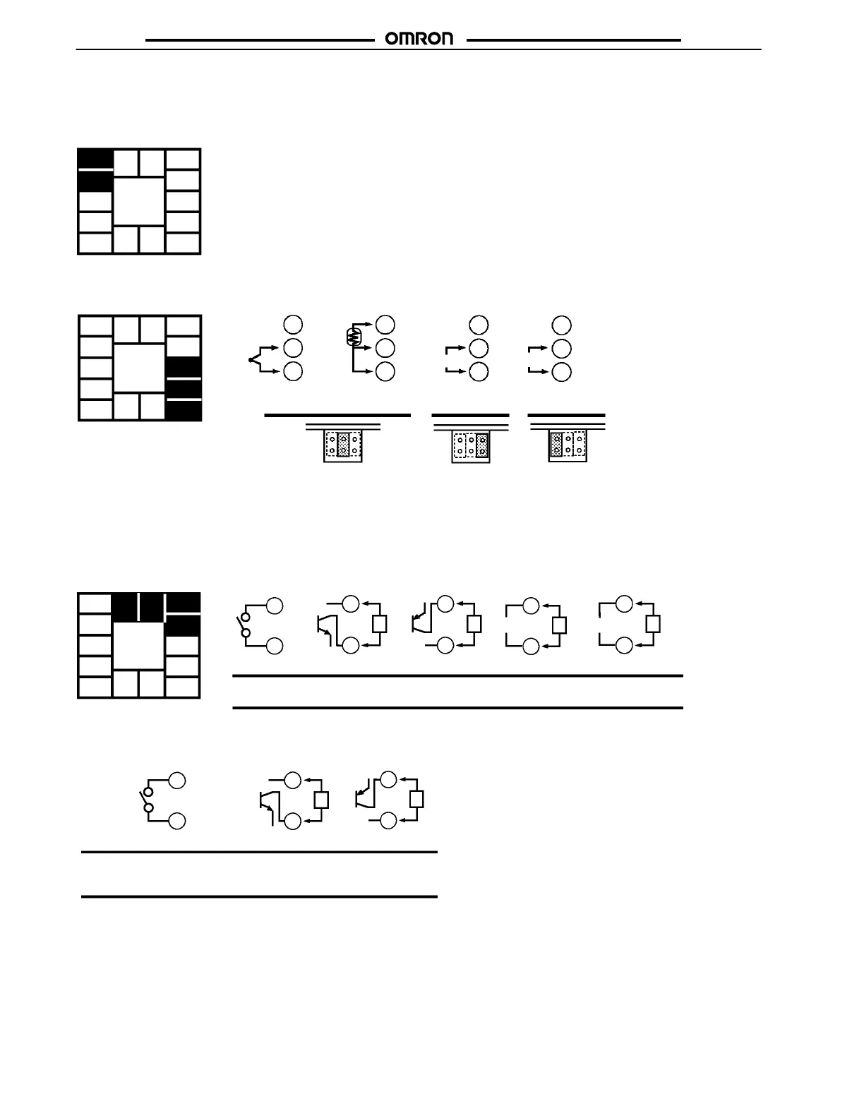
J E5CK-T WIRING
Power Supply
Input 100 to 240 VAC or AC/DC 24 V to terminal numbers 4 and 5 according to the specification.
5
4
3
2
1
10
9
8
7
6
13 14
11 12
Input
Connect the input to terminal numbers 6 to 8 as follows according to the input type.
8
7
6
8
7
6
8
7
6
8
7
6
-
+
-
+
-
+
VmA
TC ⋅ PT V I
Thermocouple Platinum resistance
thermometer
Voltage input Current input
5
4
3
2
1
10
9
8
7
6
13 14
11 12
Match the inputs with the internal jumper settings for each input type. For thermocouple or platinum resistance thermometer inputs, set
the inputs to a common position (TC/PT) as the temperature input.
Control Output
Terminal numbers 11 and 12 are for control output 1 (OUT1). The five output types and internal equalizing circuits are available according
to the output board.
5
4
3
2
1
10
9
8
7
6
13 14
11 12
11
12
11
12
L
11
12
L
11
12
L
11
12
L
E53-R4R4 E53-Q4R4
E53-Q4Q4
E53-Q4HR4
E53-Q4HQ4H
E53-V44R4 E53-C4R4
E53-C4DR4
NPN PNP 0 to 10 V 4 to 20mA
+v
+
-
+
-
+
-
+
-
GND
mA
Relay
V
+v
GND
Terminal numbers 9 and 10 are for control output 2 (OUT2). The three output types and internal equalizing circuits are available according
to the output board.
10
9
10
9
L
10
9
L
+V
+
-
+
-
GND
E53-Q4Q4 E53-Q4HQ4H
NPN PNP
E53-R4R4 /E53-V44R4
E53-Q4R4 /E53-C4R4
E53-Q4HR4/E53-C4DR4
Relay
+V
GND