E5CK-T E5CK-T
171
Specifications
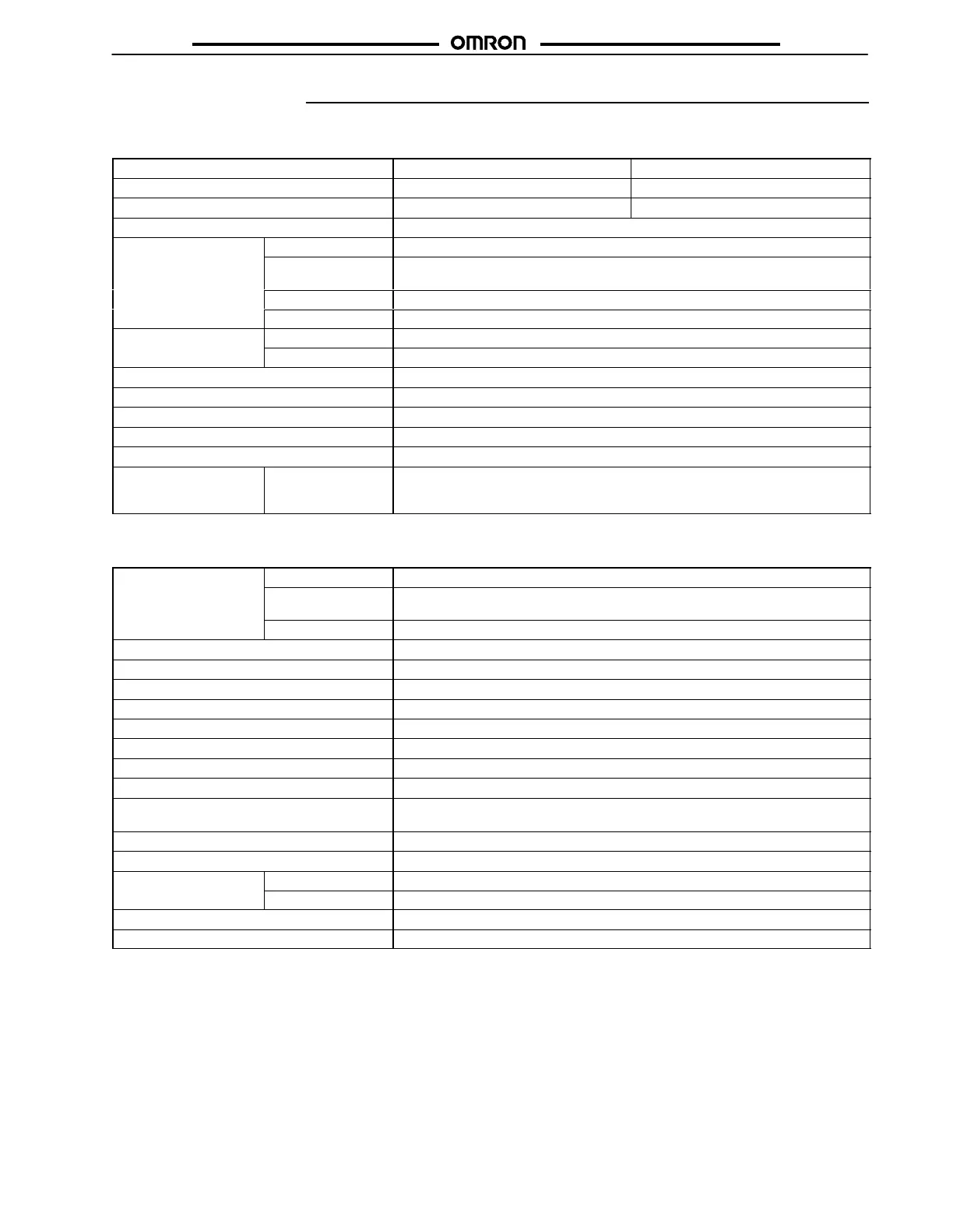
J RATINGS
Model E5CK-T (Standard) E5CK-T (24 V Type)
Supply voltage 100 to 240 VAC, 50/60 Hz 24 VAC/VDC, 50/60 Hz
Power consumption 15 VA 6 VA, 3.5 W
Operating voltage range 85% to 110% of rated supply voltage
Input
Thermocouple K, J, T, E, L, U, N, R, S, B, W, PLII
Platinum resistance
thermometer
JPt100, Pt100
Current input 4 to 20 mA, 0 to 20 mA
Voltage input 1 to 5 V, 0 to 5 V, 1 to 10 V
Input impedance
Current input 150 Ω
Voltage input 1 MΩ min.
Control output According to Output Board (see Output Board Ratings and Characteristics)
Auxiliary output SPST-NO, 1 A at 250 VAC (resistive load)
Control method ON/OFF or advanced PID control
Setting method Digital setting using front panel keys or communications features
Indication method 7-segment digital display and LEDs
Additional functions Standard Manual output, heating/cooling control, SP limiter, loop burnout alarm, MV limiter,
MV change rate limiter, input digital filter, input shift, run/reset, protect functions,
scaling function
J CHARACTERISTICS
Indication accuracy
Thermocouple ±0.3% of indication value or ±1°C, whichever greater, ±1 digit max.
(See Note 1)
Platinum resistance
thermometer
±0.2% of indication value or ±0.8°C, whichever greater, ±1 digit max.
Analog input ±0.2% of indication value, ±1 digit max.
Hysteresis 0.01% to 99.99% FS (in units of 0.01% FS)
Proportional band (P) 0.1% to 999.9% FS (in units of 0.1% FS)
Integral (reset) time (I) 0 to 3,999 s (in units of 1 s)
Derivative (rate) time (D) 0 to 3,999 s (in units of 1 s)
Control period 1 to 99 s (in units of 1 s)
Manual reset value 0.0% to 100.0% (in units of 0.1%)
Alarm setting range –1,999 to 9,999 or –199.9 or 999.9 (decimal point position dependent on input type)
Set time 0 to 99 hrs 59 min or 0 to 99 min 59 s
Program capacity 1 pattern, 16 steps (possible to use up to 4 patterns with the communications func-
tion.)
Programming method Time or ramp setting method
Time accuracy ±0.2% (±500 ms) of the set value
Sampling period
Temperature input 250 ms
(See Note 2)
Analog input 100 ms
Insulation resistance 20 MΩ min. (at 500 VDC)
Dielectric strength 2,000 VAC, 50/60 Hz for 1 min between terminals of different polarities
(This table continues on the next page.)
Note: 1. The indication accuracy of the K1, T, and N thermocouples at a temperature of -100°C max. is ±2°C ±1 digit maximum. The
indication accuracy of the U and L thermocouples at any temperature is ±2°C ±1 digit maximum.
The indication accuracy of the B thermocouple at a temperature of 400°C max. is unrestricted.
The indication accuracy of the R and S thermocouples at a temperature of 200°C max. is ±3°C ±1 digit maximum.
The indication accuracy of the W thermocouple at any temperature is (±0.3% of the indicated value or ±3°C, whichever is great-
er) ±1 digit maximum. The indication accuracy of the PLII thermocouple at any temperature is (±0.3% or ±2°C, whichever is
greater) ±1 digit maximum.
2. The sampling period of the standard model with CT and remote SP inputs is 250 ms.